Reno 10x Zoom Service Manual -V1

Confidential
Content
1. Guidance
1.1 Warnings and Cautions
1.1.1 Warnings
1.1.2 Cautions
2. General Repair Information
3. Phone Structure Diagram
3.1 Product Appearance
3.2 Phone Structure Explosive View
3.3 Explosive Map BOM
4. Disassembly Steps
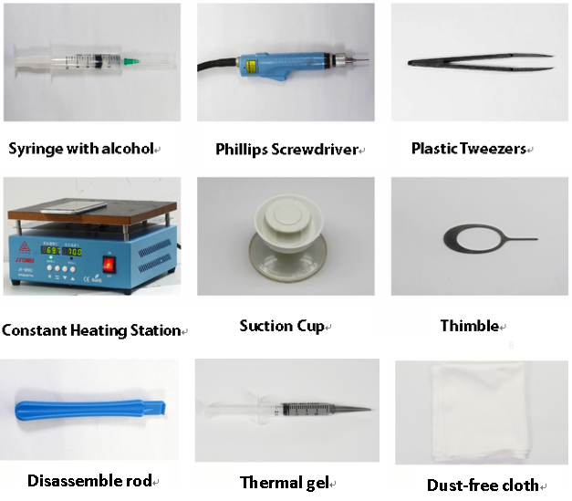
4.1 Disassembly Tools
4.2 Preparation
4.3 Disassembly Steps
5. Assembly Steps
5.1 Bill of Must-Be-Replaced Materials
5.2 Assembly Steps
6. Calibration
6.1 Fingerprint optical calibration
6.1.1 Calibration Scenario
6.1.2 Calibration Tool
6.1.3 Calibration Method
6.2 Motor Hall Calibrate
6.2.1 Calibration Scenario
6.2.2 Calibration Method
7. Function Test
7.1 Test Path
7.2 Test Requirements
8. General Cautions
1. Guidance
The purpose of this document is only to guide OPPO technicians to carry out maintenance service to OPPO products. The content shall be keep in confidential, only avail be able to OPPO authorized service centers, and cannot be provided to third parties without authorization. Please follow the regulations and the guidance for maintenance service. For any problems, please contact China HQ in time.
1.1 Warnings and Cautions
1.1.1 Warnings
1. Care must be taken on installation in vehicles fitted with electronic engine management systems and ABS (Anti–skid Braking Systems). Under certain fault conditions, emitted RF energy can affect their operation. If necessary, consult the vehicle dealer/manufacturer to determine the immunity of vehicle electronic systems to RF energy.
2. Phones must not be operated in areas likely to contain potentially explosive atmospheres, e.g. petrol stations (service stations), blasting areas etc.
3. Operation of any radio transmitting equipment, including cellular telephones, may interfere with the functionality of inadequately protected medical devices. Consult a physician or the manufacturer of the medical device if you have any questions. Other electronic equipment may also be subject to interference.
1.1.2 Cautions
1. Repair services and calibrations must be undertaken by qualified personnel only.
2. Use only approved components as specified in the parts list.
3. Ensure all components, modules screws and insulators are correctly re-fitted after servicing and alignment.
4. Electrostatic discharge is the main cause of damage to sensitive components of electronic products. Service centers must operate in accordance with OPPO's requirements for ESD protection. Ensure all work is carried out at an ESD workstation and that an ESD wristband is worn.
2. General Repair Information
1. Ensure all work is carried out at an ESD workstation and that an ESD wristband is worn before starting maintenance.
2. Wear ESD gloves to avoid oil stains and fingerprints.
3. Use protective films to protect the display, camera, camera lens to prevent dust and scratches.
4. Use a clean cloth, ESD brush and alcohol (Concentration above 95%) for appearance cleaning. Do not use other items (such as an eraser) for cleaning to prevent the protective layer from being scratched, which may lead to oxidation and corrosion.
5. Faulty welded mechanical parts (except shield cover and shield frame parts) can only be replaced and not repairable.
6. Use accessories provided by OPPO.
7. Check the contacts or solder joints of devices that may cause simple faults (e.g. soldered interfaces or switches). Re-weld if necessary (only for service centers where lead-free soldering is available) and clean the flux remaining after soldering.
8. Use the equipment provided by OPPO to test the phone (e.g. When the charging function of the device is abnormal, do use the original OPPO adapter to test to ensure the accuracy of the test results).
9. Fill in the fault phenomenon code and fault reason code according to the actual situation, and accurately enter the replacement material code in the CRM system (Refer to the Smart Phone Fault Reason Matching Code List if necessary).
10. For more information about products, please visit the company FTP server: ftp://ftpex.oppo.com:919/
3. Phone Structure Diagram
3.1 Product Appearance
As shown in Figure 3-1-1
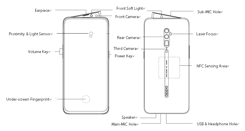
Figure 3-1-1
3.2 Phone Structure Explosive View
As shown in Figure 3-2-1
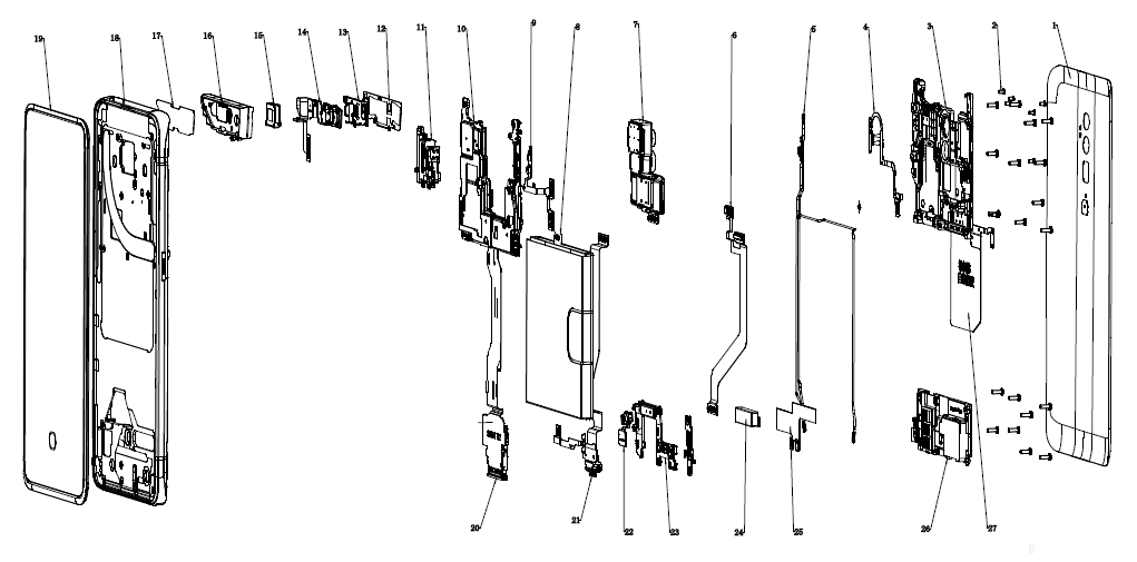
Figure 3-2-1
3.3 Explosive Map BOM
| No. | Material Name(After-sales) | Physical Figure | Specifications | QTY | Unit | |
| 1 | Battery Cover | 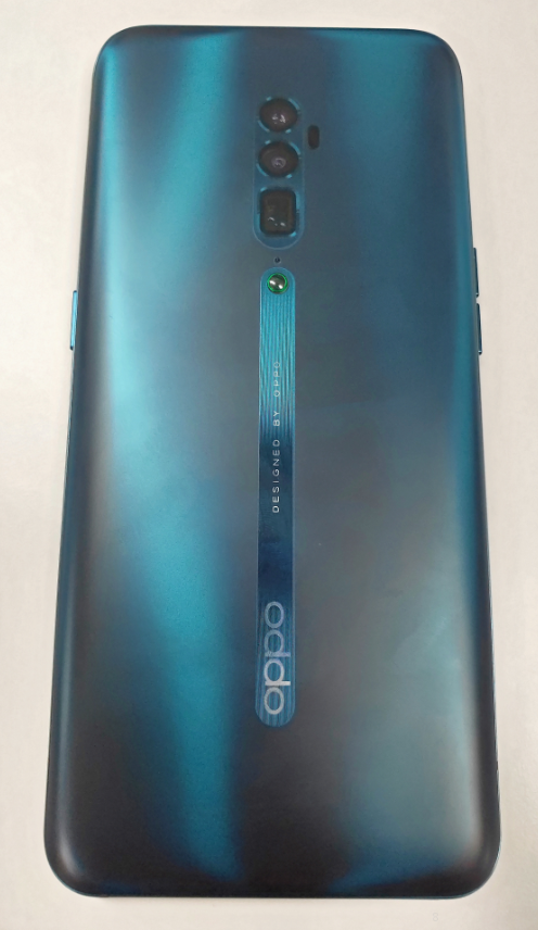 | 1) Battery cover assembly | 1 | PCS | |
| 2 | Screws | 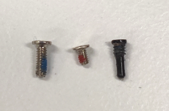 | 2)Screws | 25 | PCS | |
| 3 | Mainboard bracket assembly | 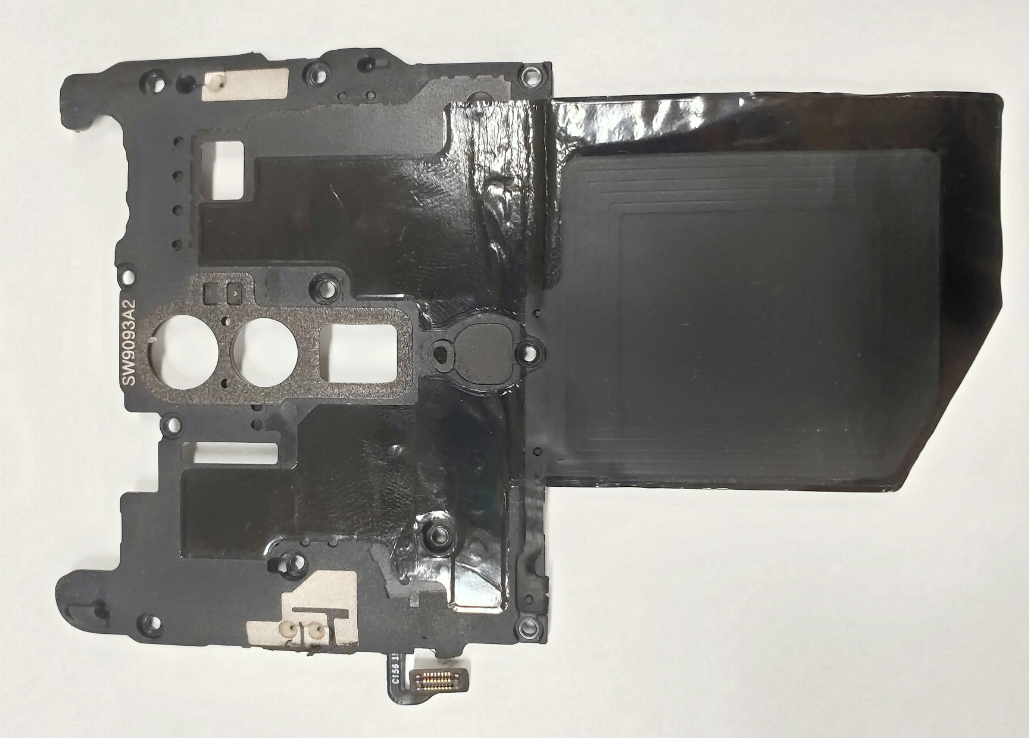 | 3)Mainboard bracket | 1 | PCS | |
| 4)Laser focus FPC(XBD186-0-patch 18115) | 1 | PCS | ||||
| NFC FPC | 1 | PCS | ||||
| 4 | RF cable | 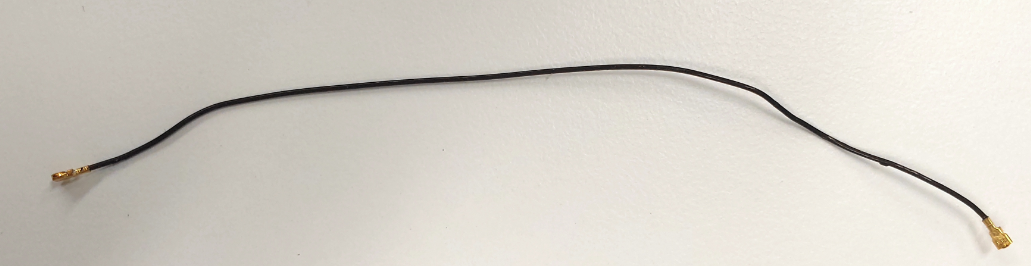 | 5)RF cable | 3 | PCS | |
| 5 | FPC patch semi-finished products (CBD186-0-Patch 18115) | 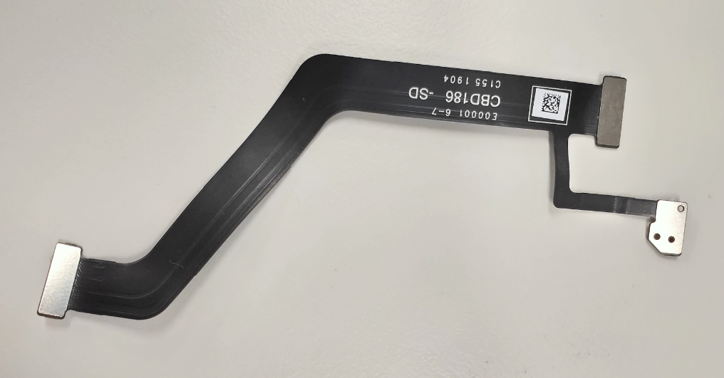 | 6)Third MIC FPC | 1 | PCS | |
| 6 | Camera assembly | 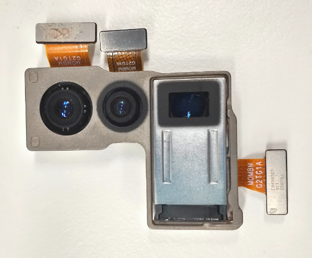 | 7)Rear camera assembly | 1 | PCS | |
| Camera conductive cloth (main) | 1 | PCS | ||||
| 7 | Battery assembly | 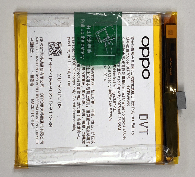 | 8)Lithium charge | 1 | PCS | |
| Battery anti-static bag | 1 | PCS | ||||
| 8 | Push rod bracket assembly | 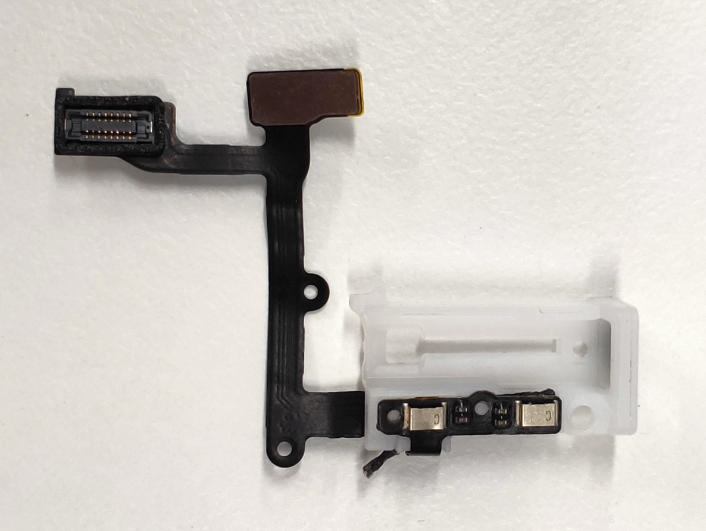 | 9)Light induction FPC (JBD186-0 18115) | 1 | PCS | |
| Push rod bracket | 1 | PCS | ||||
| 9 | Mainboard assembly | 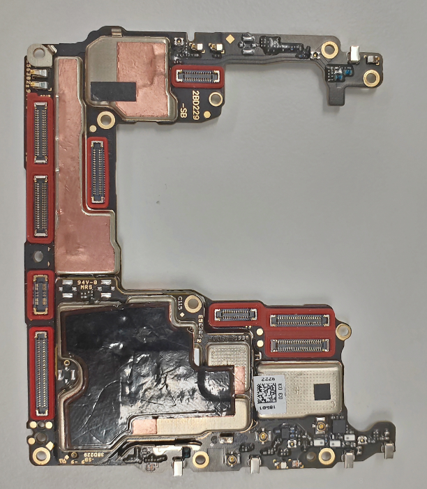 | 10)Mainboard semi-finished products | 1 | PCS | |
| Mainboard test point PET film (right) | 1 | PCS | ||||
| Mainboard test point PET film (left) | 1 | PCS | ||||
| 10 | Motor assembly | 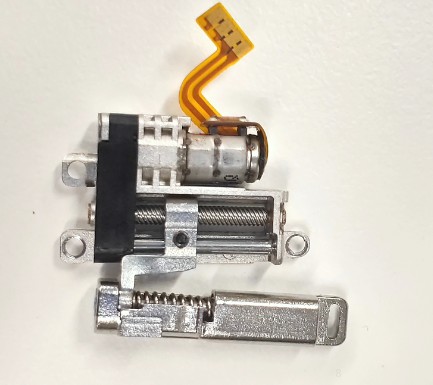 | 11)Motor assembly (including gearbox) | 1 | PCS | |
| Motor top double-sided tape | 1 | PCS | ||||
| 11 | Small middle frame assembly | 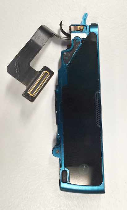 | 12)Small middle frame metal decoration | 1 | PCS | |
| 13)Small middle frame bracket | 1 | PCS | ||||
| 14)R board assembly | 1 | PCS | ||||
| 15)Receiver | 1 | PCS | ||||
| 16)Small middle frame component | 1 | PCS | ||||
| 17)Small middle frame glass decoration | 1 | PCS | ||||
| Screws | 3 | PCS | ||||
| Camera FPC foam (front) | 1 | PCS | ||||
| Front BTB bracket | 1 | PCS | ||||
| Front BTB board bracket | 1 | PCS | ||||
| Camera | 1 | PCS | ||||
| Receiver bracket FPC pressure board bracket | 1 | PCS | ||||
| 12 | Display assembly | 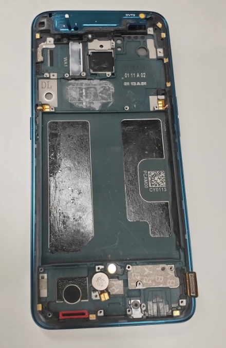 | Touch screen protection film | 1 | PCS | |
| 18)Middle frame component | 1 | PCS | ||||
| 19)Touch Screen | ||||||
| LCM FPC protective silicone case | 1 | PCS | ||||
| LCM water proof silicone case | 1 | PCS | ||||
| PCB patch semi-finished products (6BD229-0-Patch 18503) | 1 | PCS | ||||
| FPC patch semi-finished products (MBD229-0-Patch 18503) | 1 | PCS | ||||
| 13 | FPC Semi finished product(LBD186-0 18115) | 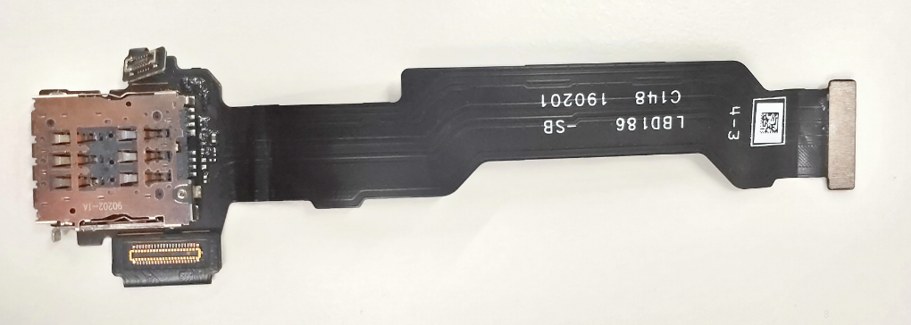 | 20)SIM card support FPC components | 1 | PCS | |
| 14 | FPC Semi finished product(UBD186-0 18115) | 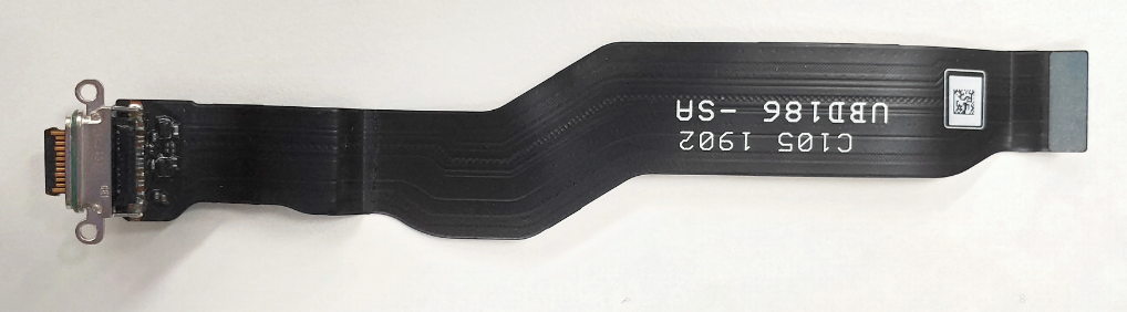 | 21)USB FPC | 1 | PCS | |
| 15 | Fingerprints sensor module | 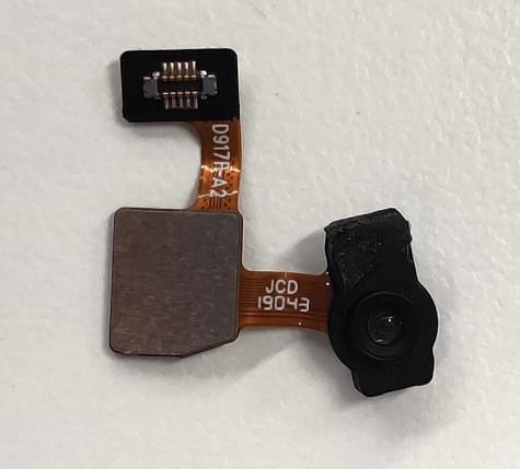 | 22)Screen fingerprint component | 1 | PCS | |
| 16 | Antenna small board assembly | 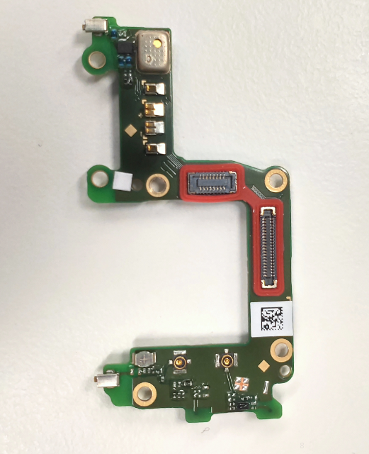 | Waterproof sticker | 1 | PCS | |
| 23)Small board semi-finished product | 1 | PCS | ||||
| 17 | Linear motor assembly | 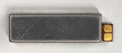 | 24)Linear motor | 1 | PCS | |
| Linear motor foam | 1 | PCS | ||||
| Double-sided tape for Motor | 1 | PCS | ||||
| 18 | Speaker assembly | 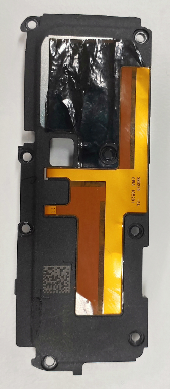 | 25)SAR FPC | 1 | PCS | |
| 26)BOX component | 1 | PCS | ||||
| BOX Assembly Graphite sheet | 1 | PCS |
Note:This table is used only for the name of the annotation but not for the preparation of materials. Please refer to the “Price list of Commonly-used Materials and Accessories” for the preparation.
4. Disassembly Steps
4.1 Disassembly Tools
4.2 Preparation
1. The phone must be powered off before disassembly.2. Way to Power Off:
4.3 Disassembly Steps
| Step | Content | Figure | Cautions |
|---|---|---|---|
| 1 | Disassemble the battery cover | 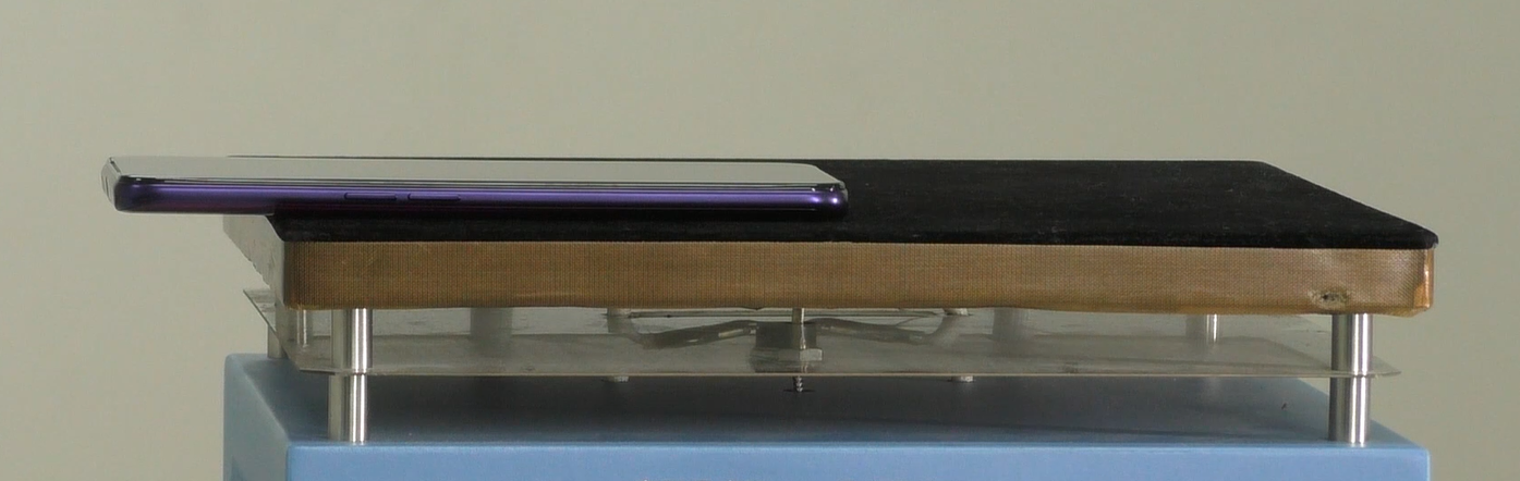 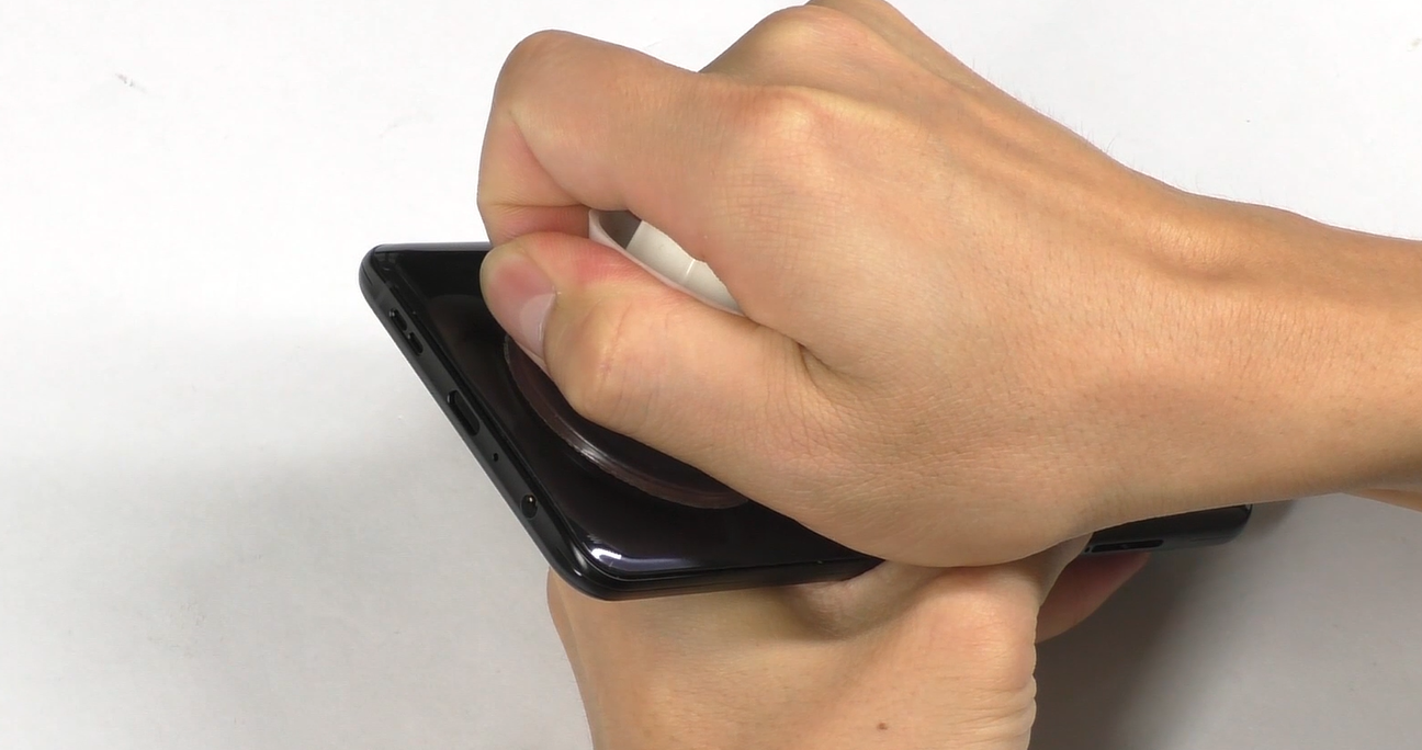 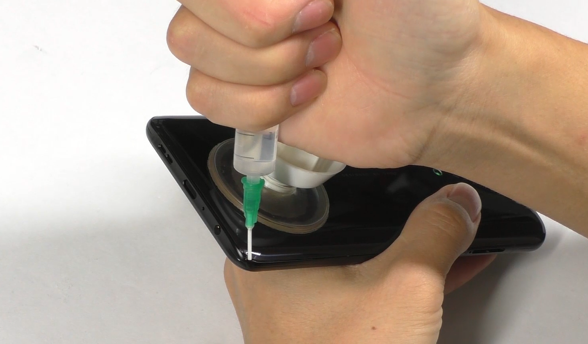 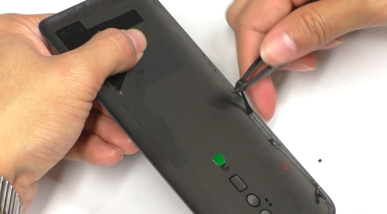 | (1) Avoid heating the camera. Heating requirements: 70 ° C -80 ° C for 5-10 mins; (2) Use the suction cup to remove the battery cover from the bottom of the phone; adjust the suction cup and strength according to the tightness when separating it. to prevent the battery cover and the middle frame from being scratched. (3) Prevent the rear camera and rear lens from being dirty when removing and installing the rear camera. |
| 2 | Disassemble the mainboard screws, bracket and the battery | 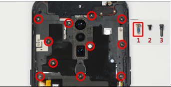 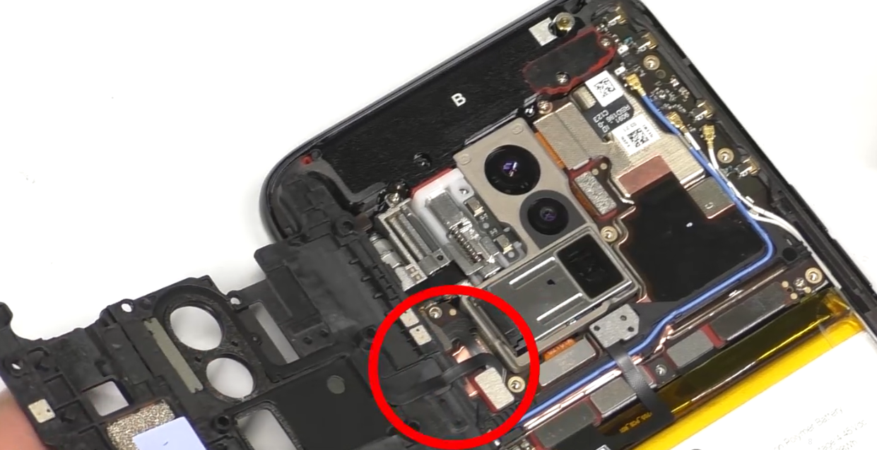 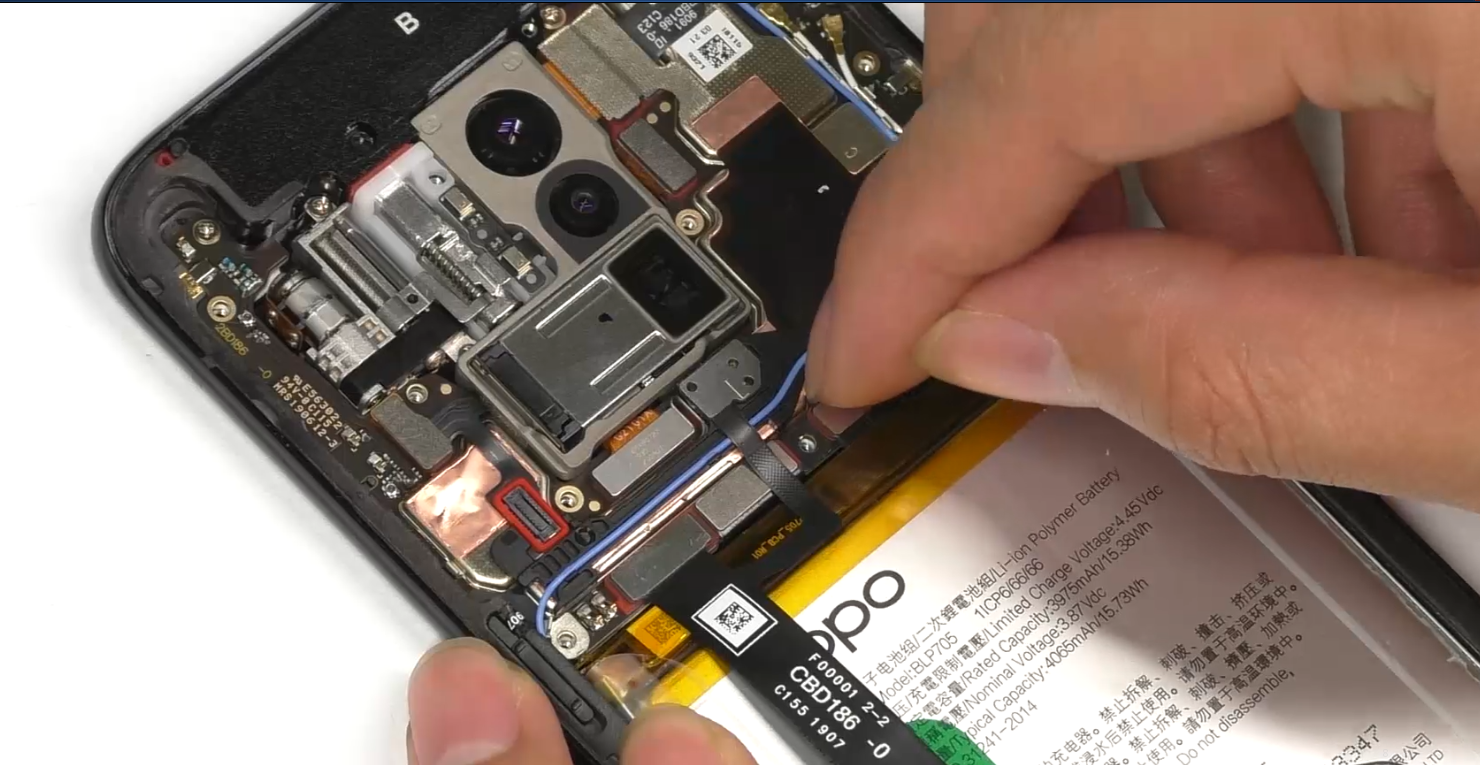 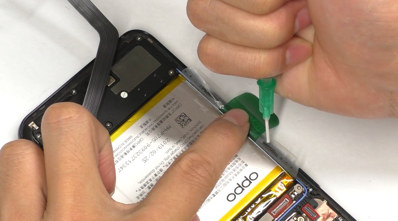 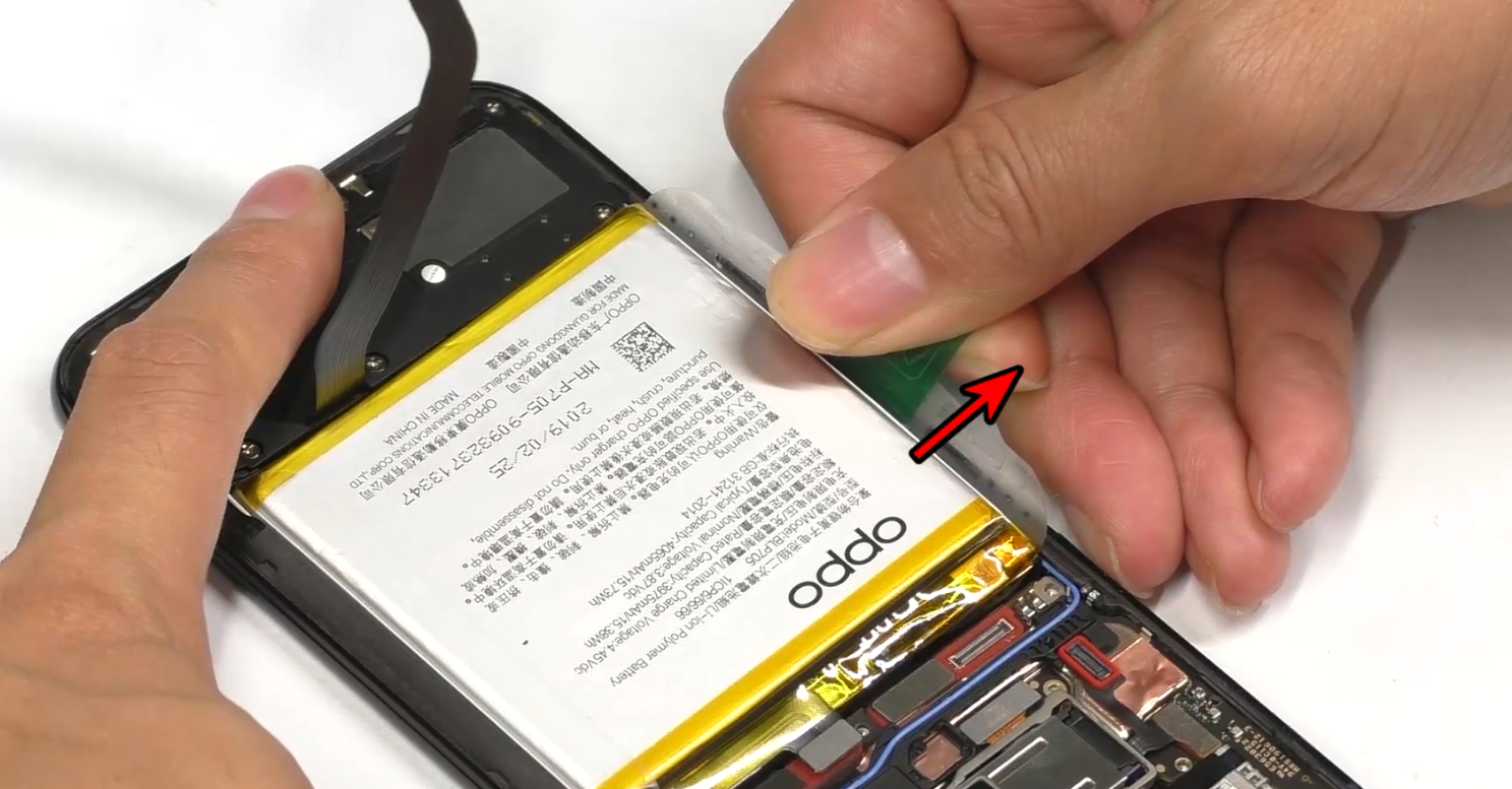 | (1)The 11 screws on the mainboard bracket are the 1# screw in the figure (The serial number for screws in the figure will be represented as #number, such as: #1). (2) Remove the mainboard bracket from the lower right corner, and avoid breaking the FPC. (3) After tearing off the easy-tore paper, add 0.2ml of alcohol to the upper and lower sides of the handle, and stand the phone for 15 seconds until the alcohol spreads; (4) Place the phone flat and pull it diagonally. Make the angle between the handle position and the battery are larger than 90°, and slowly pull the battery off. Note: Since the adhesiveness of the Reno easy tore paper is strong, avoid bending and deformation of the middle part of the battery during assembly. |
| 3 | Remove the main board end C board and the RF cable | 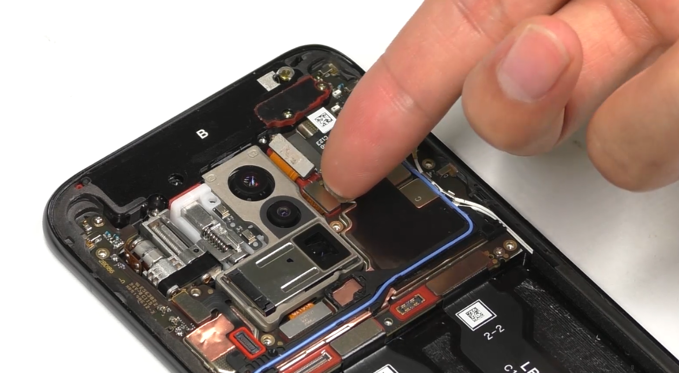 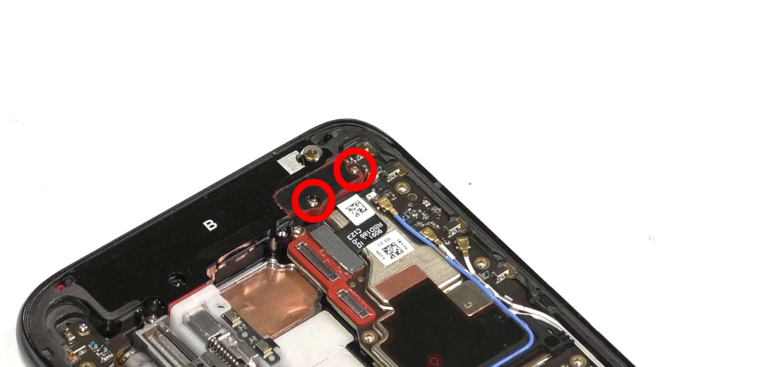 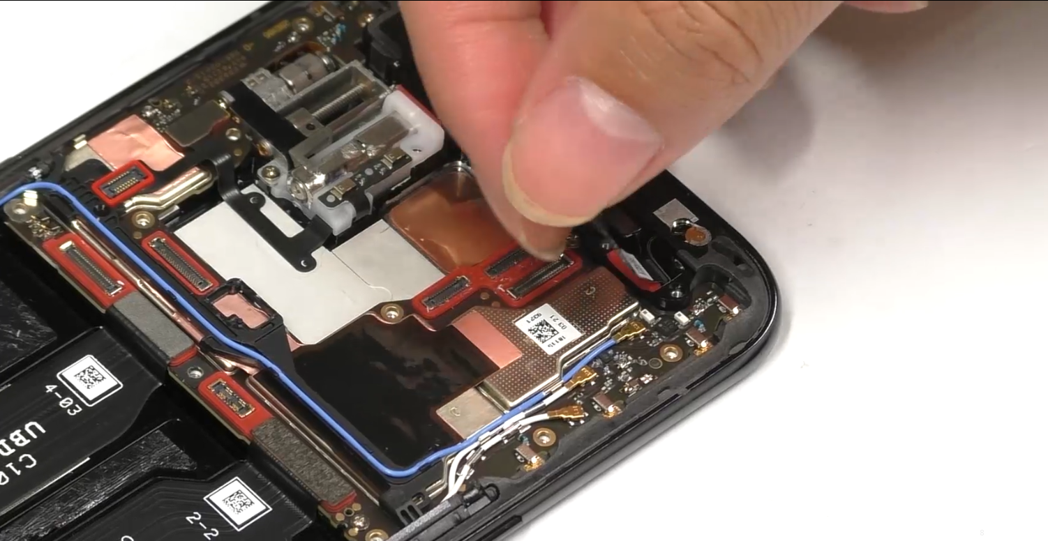 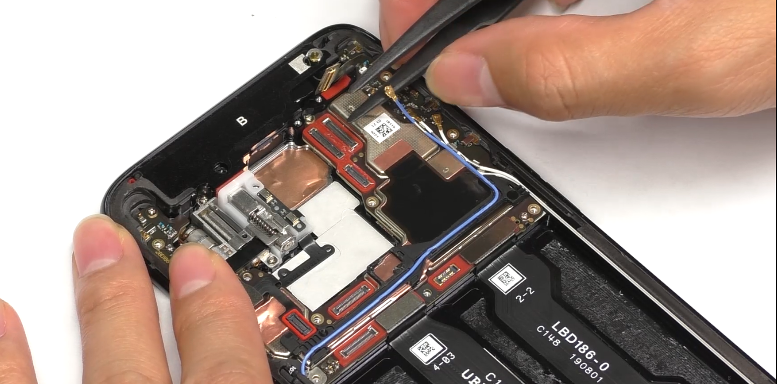 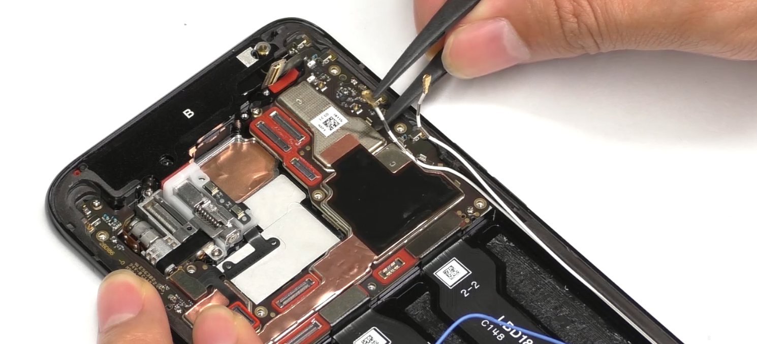 | (1) When removing the screws for FPC sealing bracket silicone sleeve, note that the screws of 2 pcs here are # 2. (2) When disassembling the RF cable, especially in the tight groove of the cable, pull it out gently to prevent the RF cable from being scratched. |
| 4 | Remove the main board end J board, L board and C board and the mainboard | 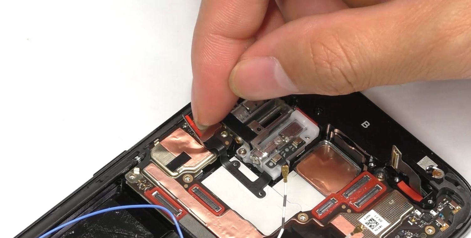 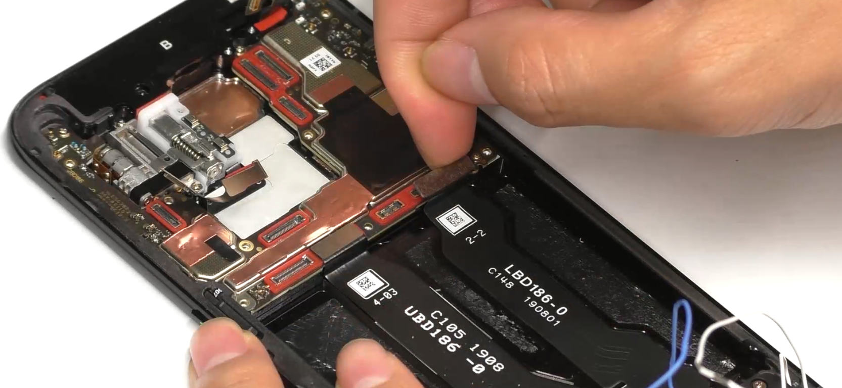 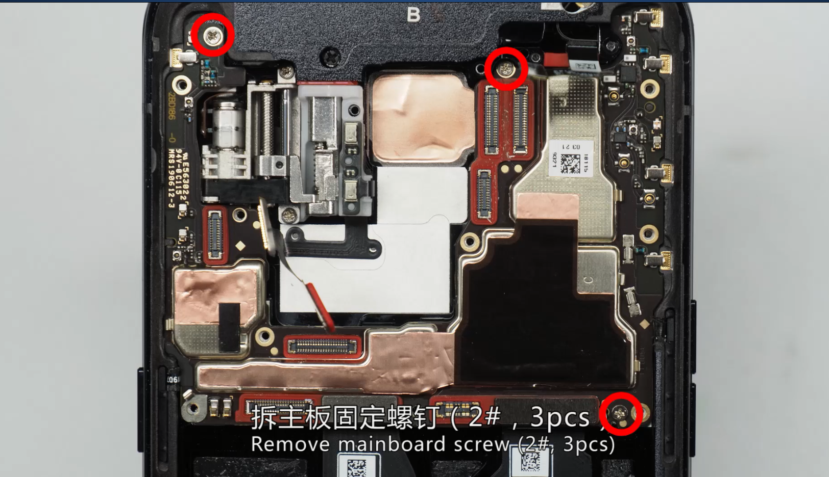 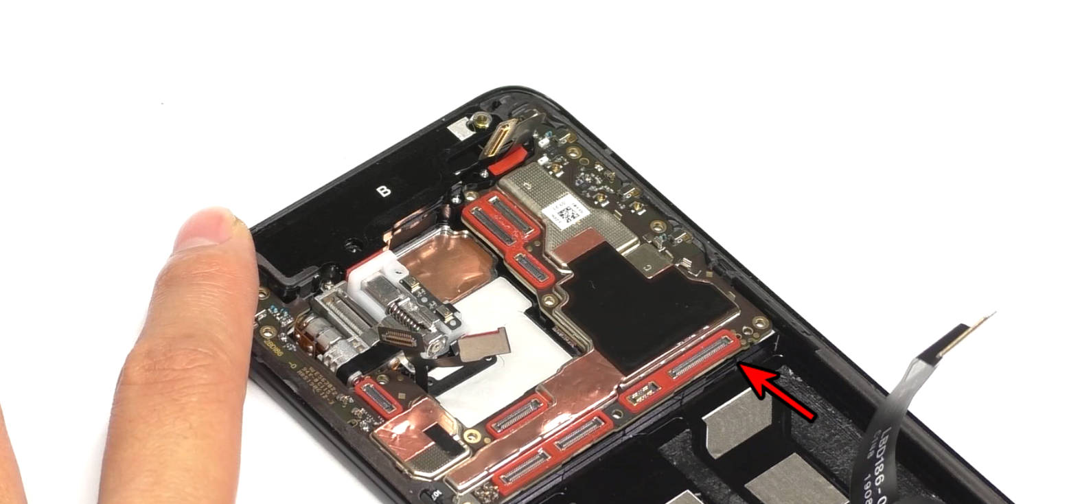 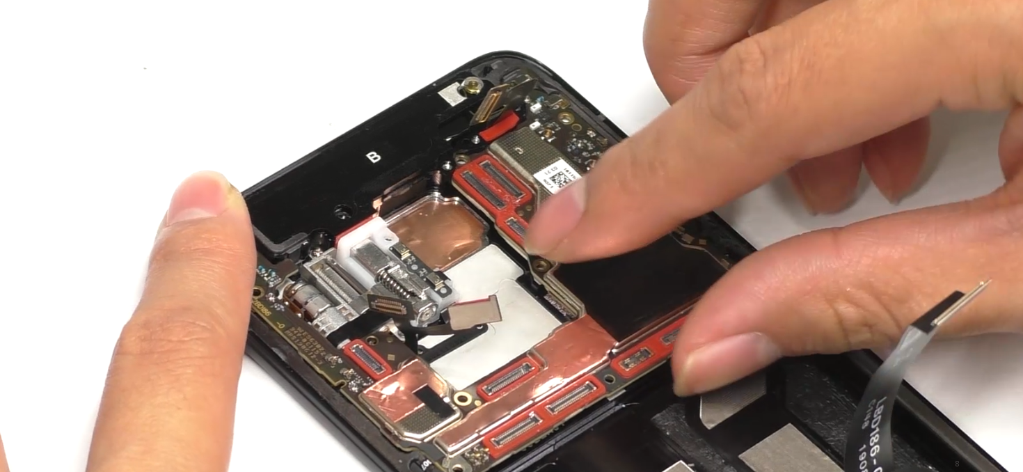 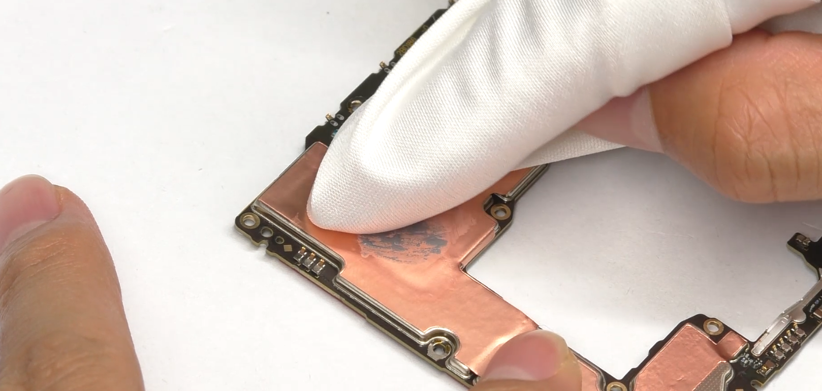 | (1) Remove the mainboard after disassembling the mainboard screws,; (2) Remove the mainboard from the lower right corner, taking care to avoid scraping the FPC and motor solder joints; (3) The thermal gel needs to be cleaned after removing the mainboard. |
| 5 | Disassemble the speaker, antenna small board end RF line and C board | 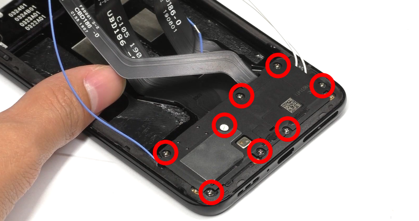 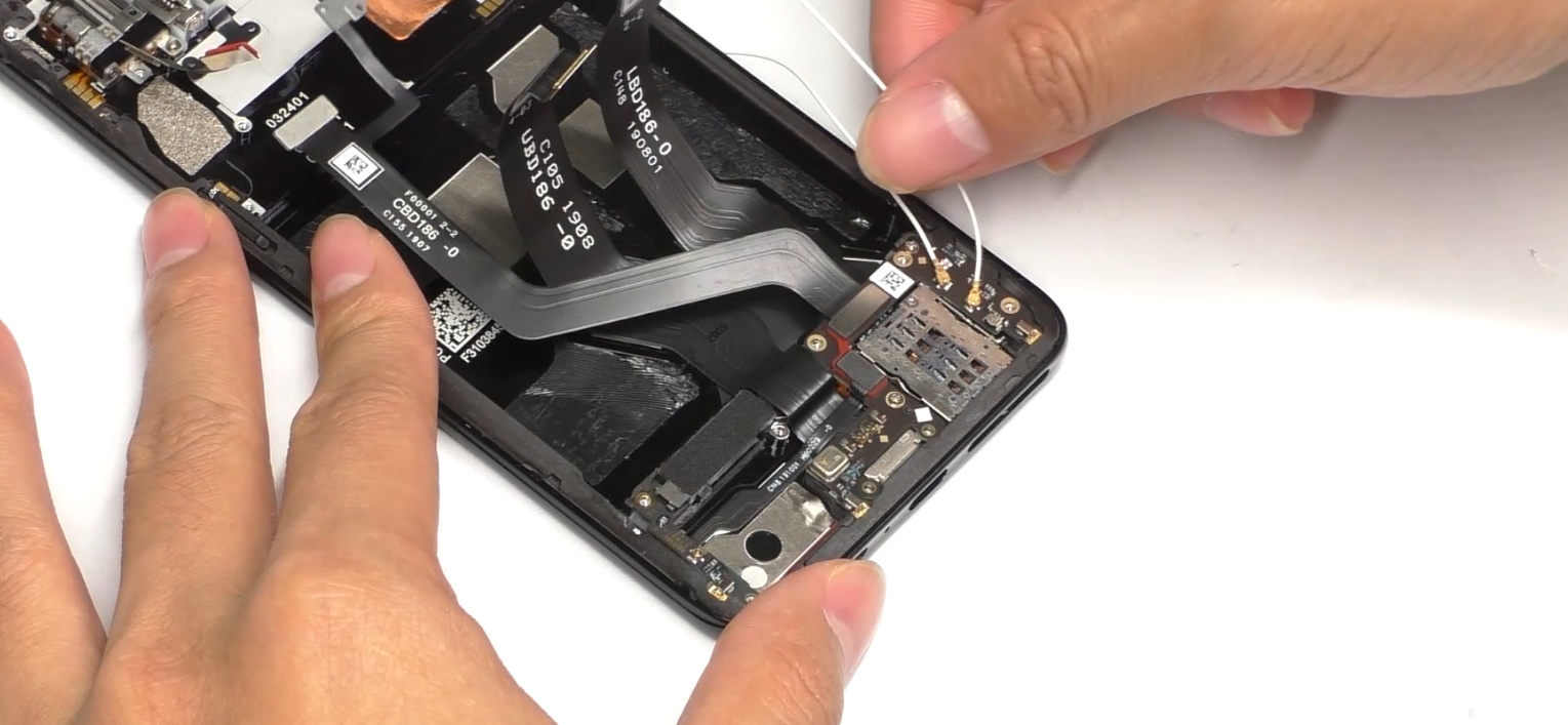 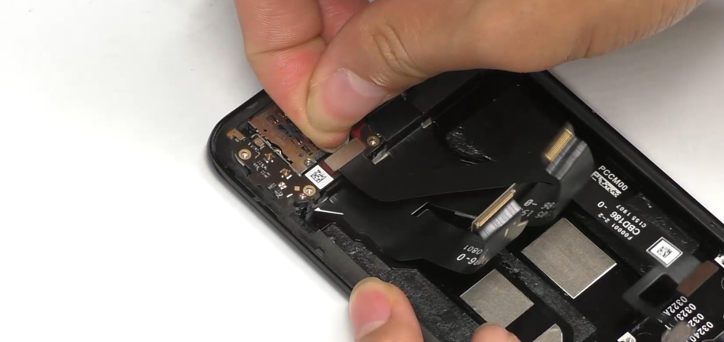 | (1) Remove the speaker #1 screws (a total of 8 screws). (2) Remove the RF cable softly. |
| 6 | Disassemble the antenna small board and U board | 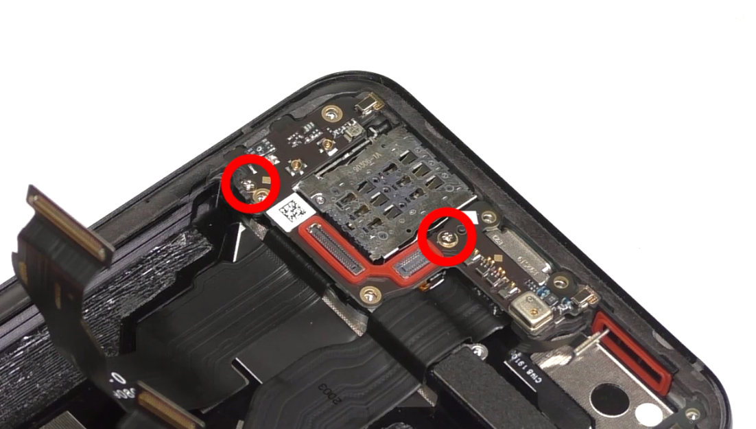 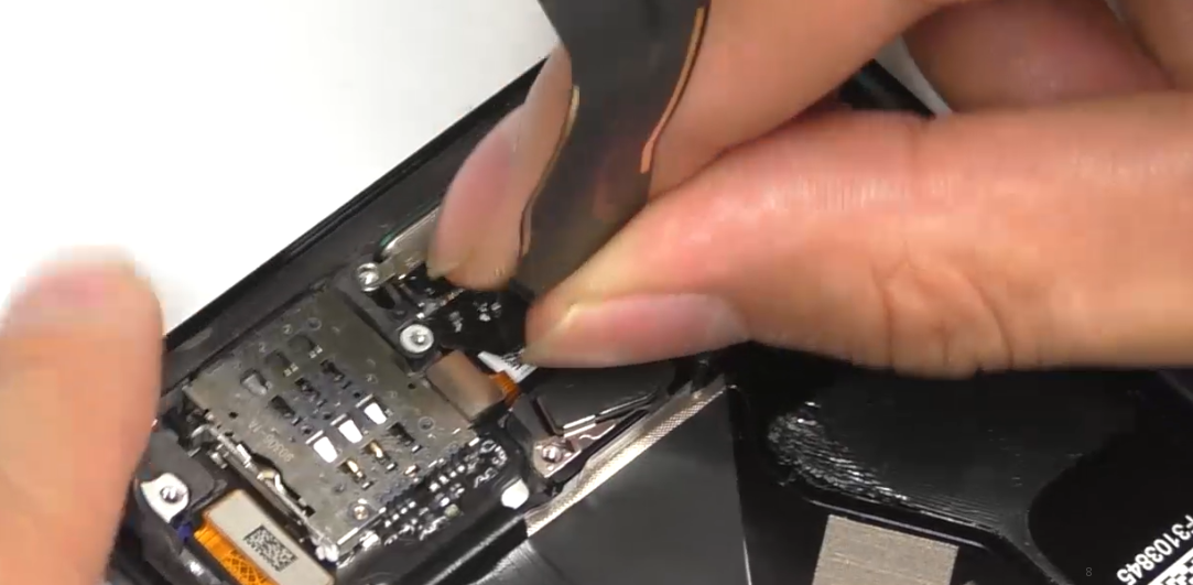 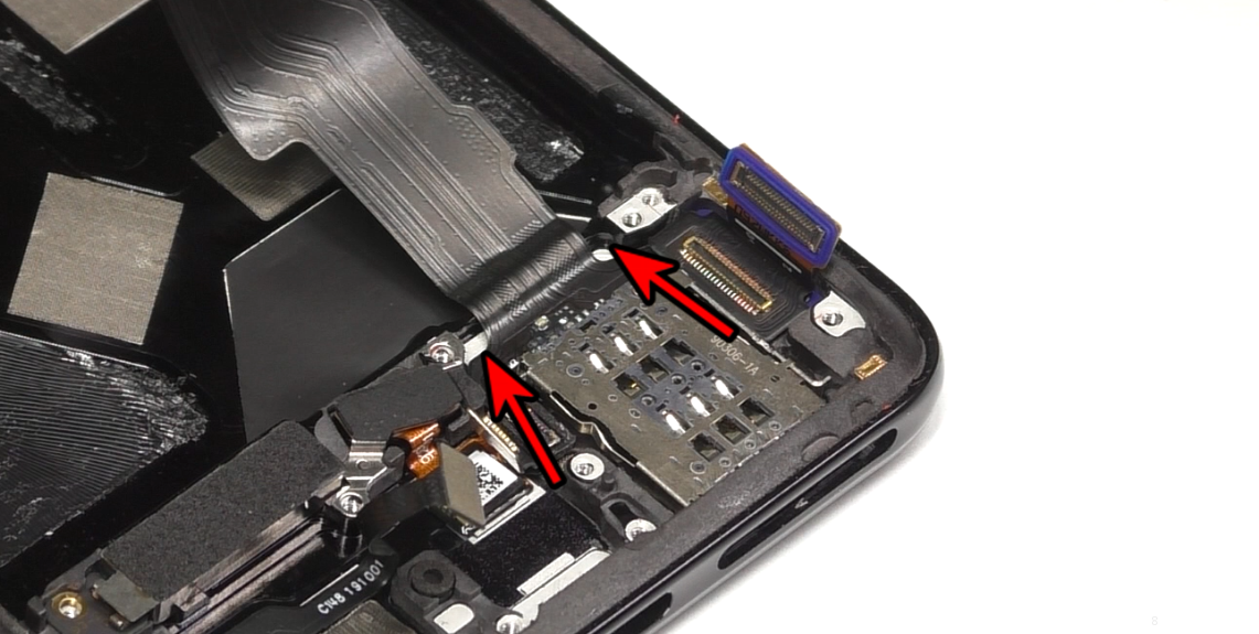 | (1) Remove screws on the antenna board before disassembling the antenna board. (2) Inject a small number of alcohol on both sides when disassembling the USB FPC. |
| 7 | Disassemble L board, remove linear motor and 6 boards | 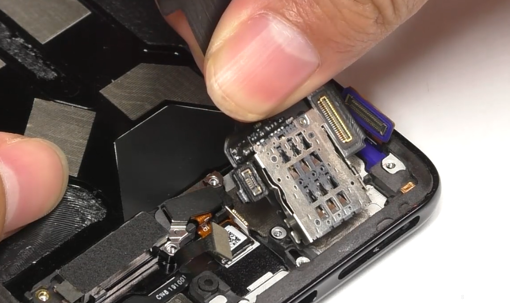 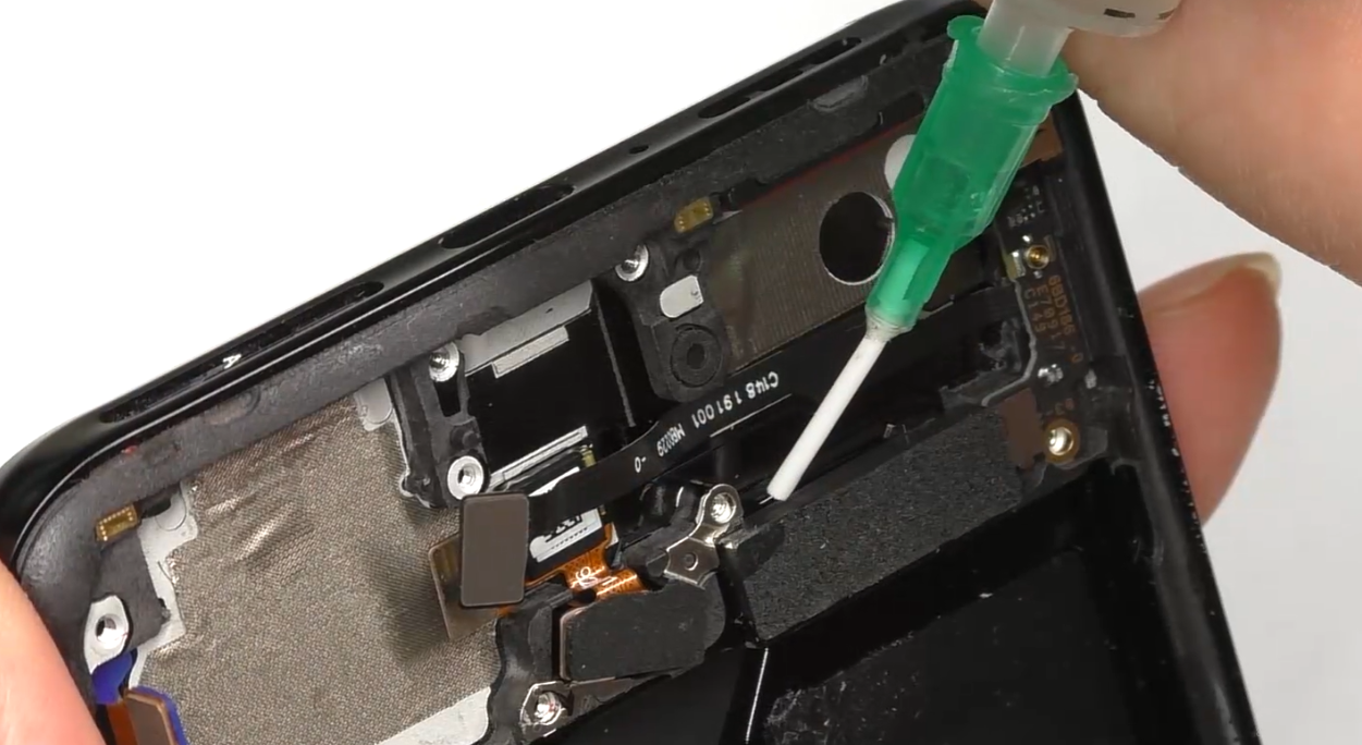 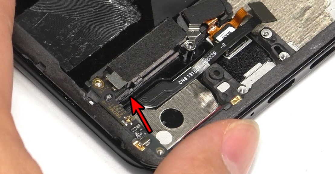 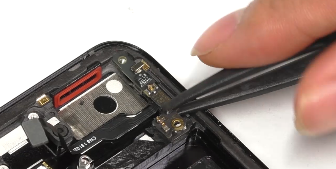 | (1) When disassembling the linear motor, stand the mobile phone sideward and add a small number of alcohol at the edge. Disassemble it in the direction of the arrow as shown in the figure. |
| 8 | Remove fingerprint module, M board | 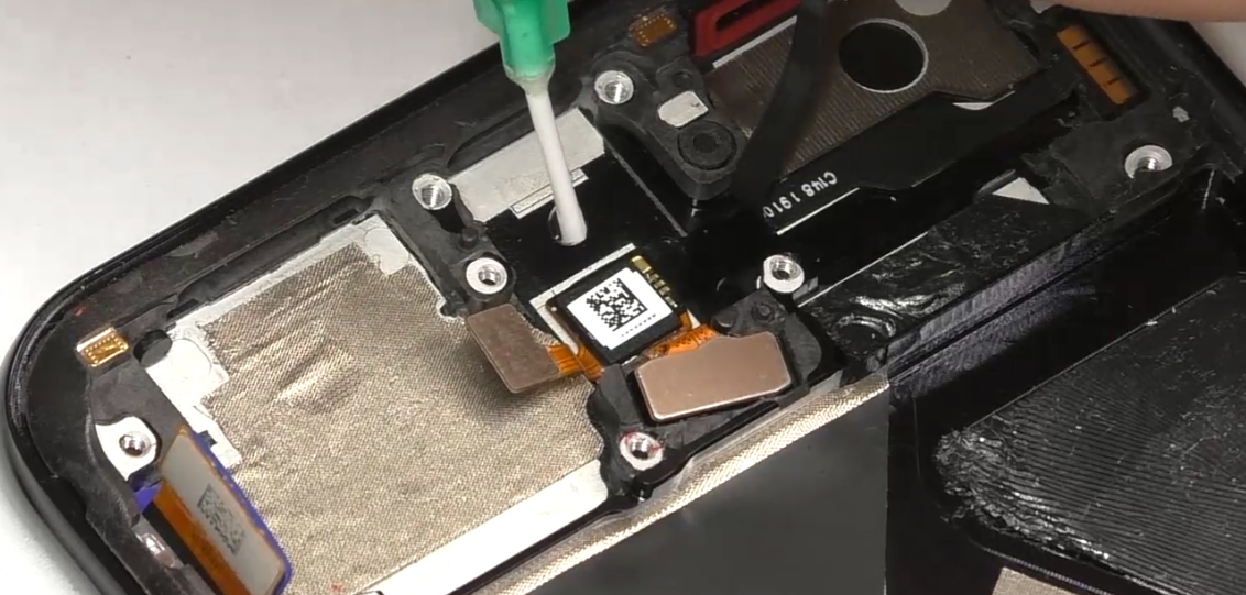 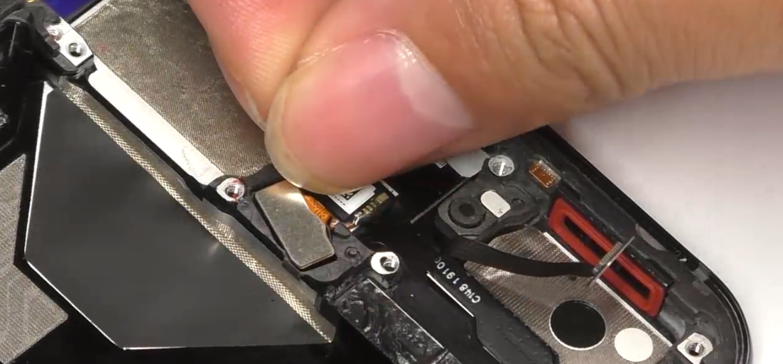 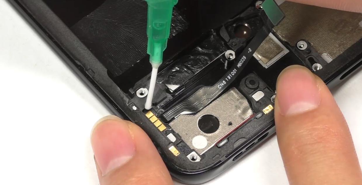 | (1) Before dropping the fingerprint module, inject a small number of alcohol from the edge of the fingerprint module IC. (2) Before disassembling the M board, first inject some alcohol from the edge to become less adhesive. |
| 9 | Disassemble motor assembly, small middle frame | 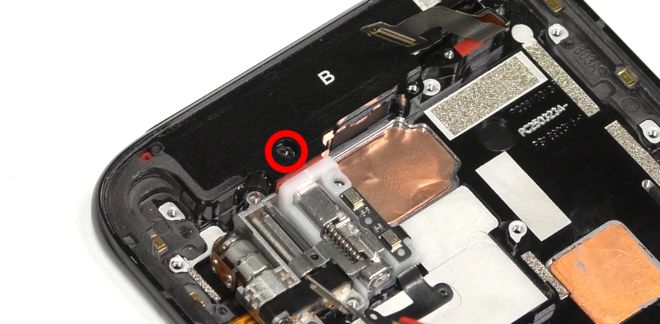 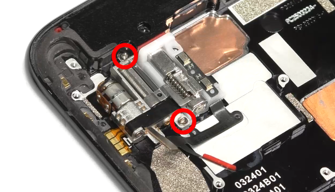 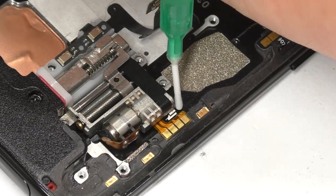 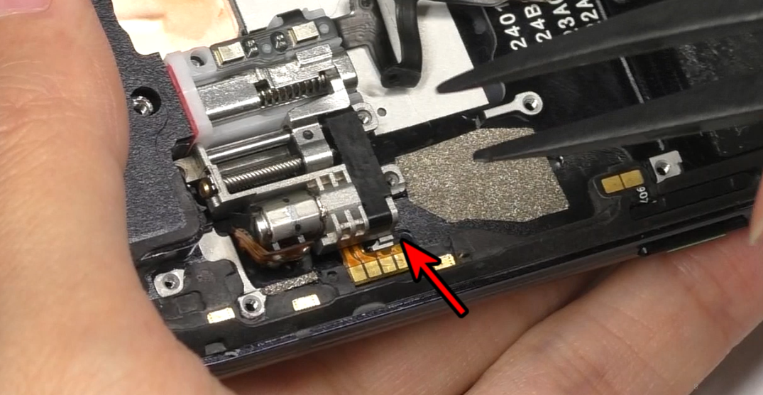 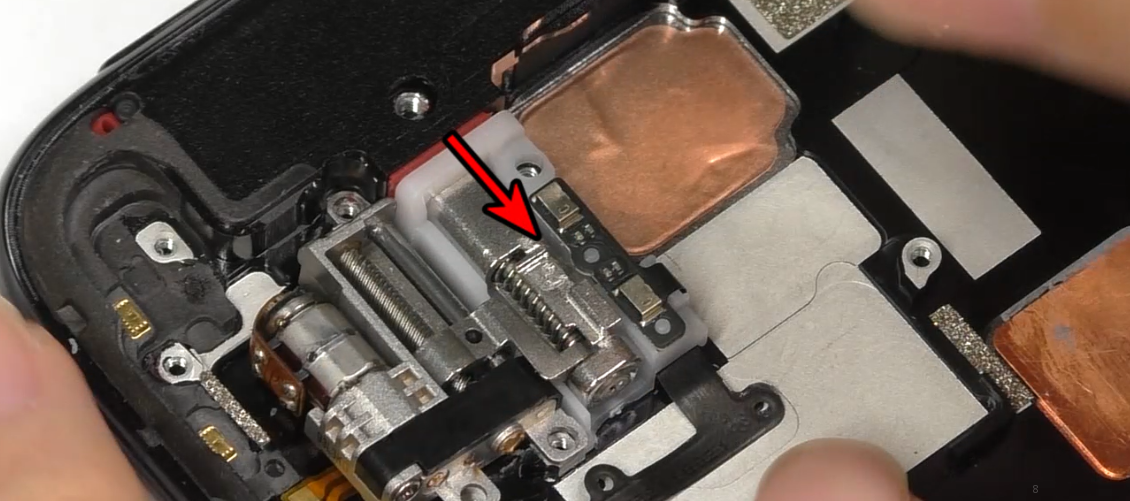 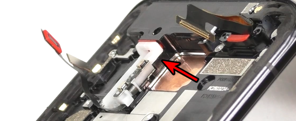 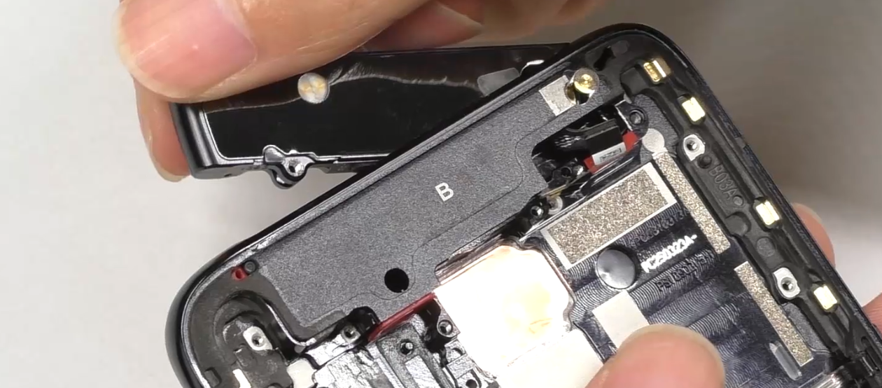 | (1) Follow the arrow direction in the figure when removing the lift motor. (2) Disassemble the small middle frame, pay attention to the screws on the frame are #3. (3) Avoid scratching the FPC when removing the small middle frame. (4) Since the small middle frame in the BOM is a single component for after sales, please refer to the steps in the disassembly video. |
5. Assembly Steps
5.1 Bill of Must-Be-Replaced Materials
| No. | Code | Material | SPEC. | QTY. |
| 1 | 4876740 | Battery easy-tore paper | BLP705 transparent | 1 |
| 2 | 2929357 | Power key bracket | BD187 | 1 |
| 3 | 2929358 | Volume key bracket | BD187 | 1 |
| 4 | 4875750 | waterproof double-sided adhesive for Battery cover | BD187 | 1 |
5.2 Assembly Steps
| Step | Content | Figure | Cautions |
|---|---|---|---|
| 1 | Install the push rod bracket, motor assembly and small middle frame | 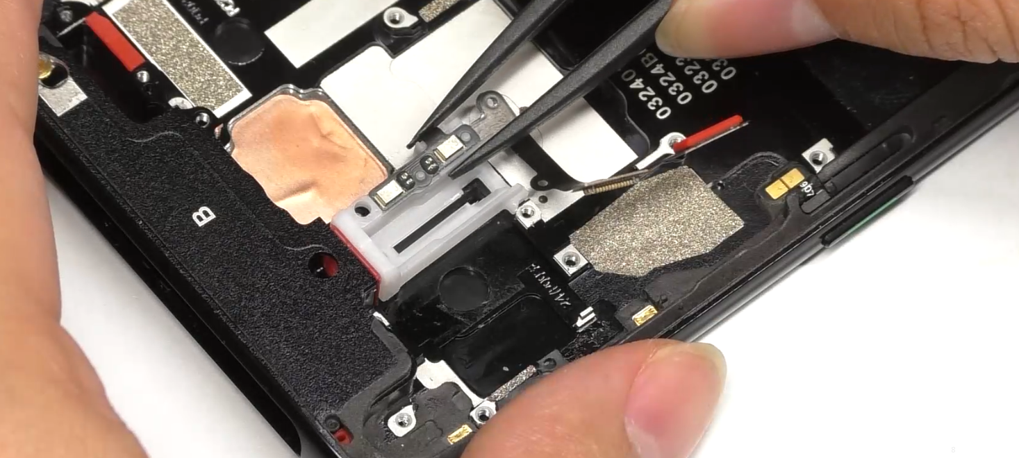 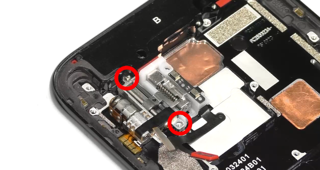 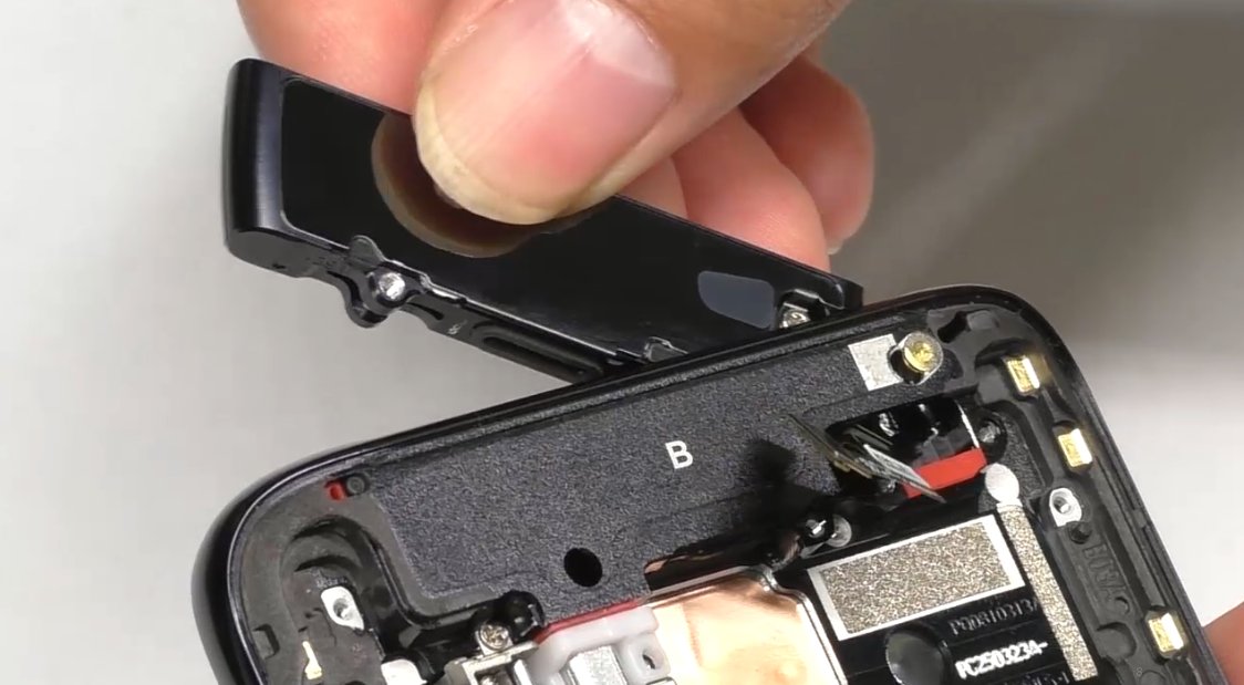 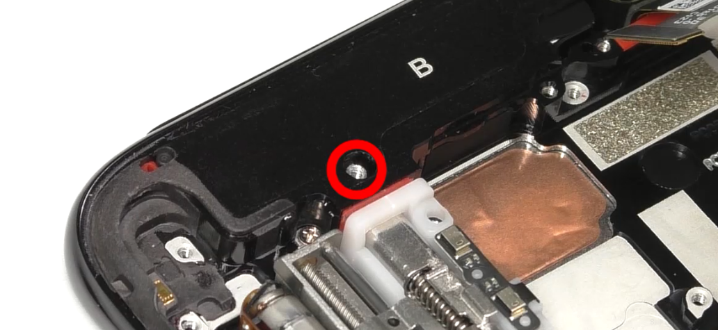 | (1) The screws for the lifting motor assembly are #2 2 pcs; (2) Avoid damaging the R-board FPC when installing the small middle frame; (3) The screw for the small middle frame shaft is #3(1pcs) ; |
| 2 | Install fingerprint sensor, M board, 6 board and linear motor | 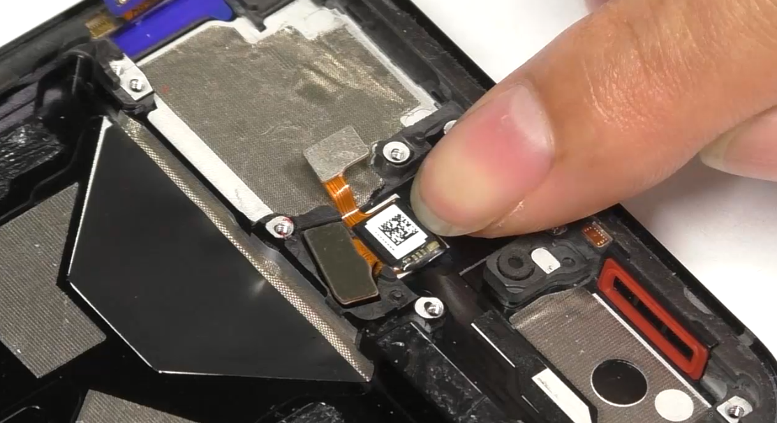 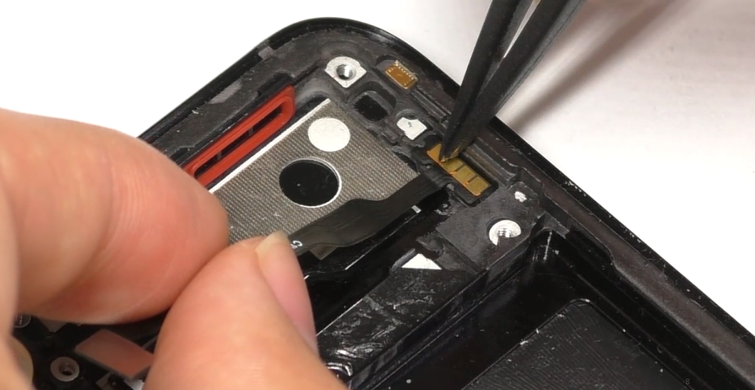 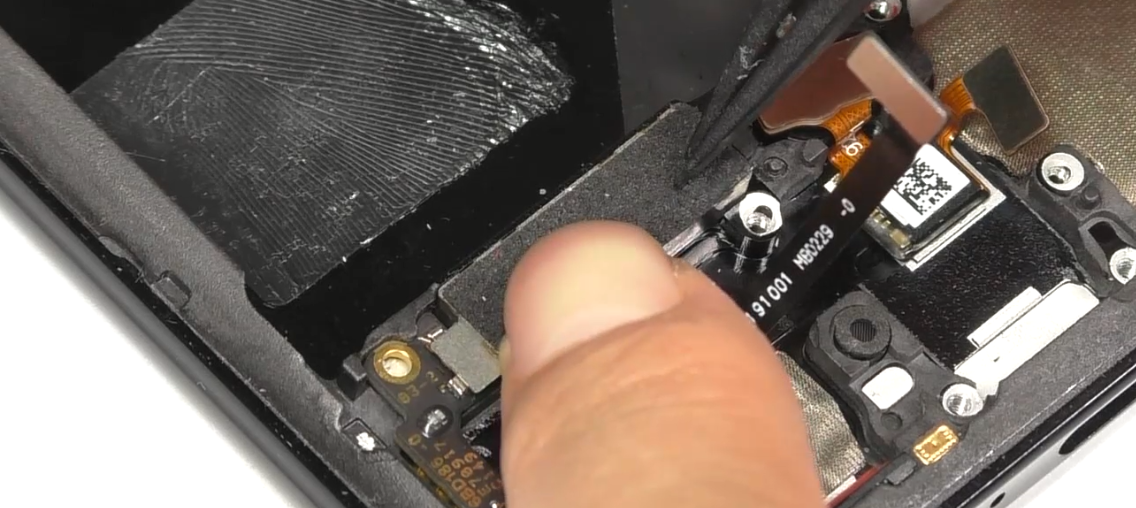 | (1) Make sure there is no foreign objects at the bottom when installing the fingerprint sensor. |
| 3 | Install L board, screen fingerprint holder, U board and A board (antenna board) | 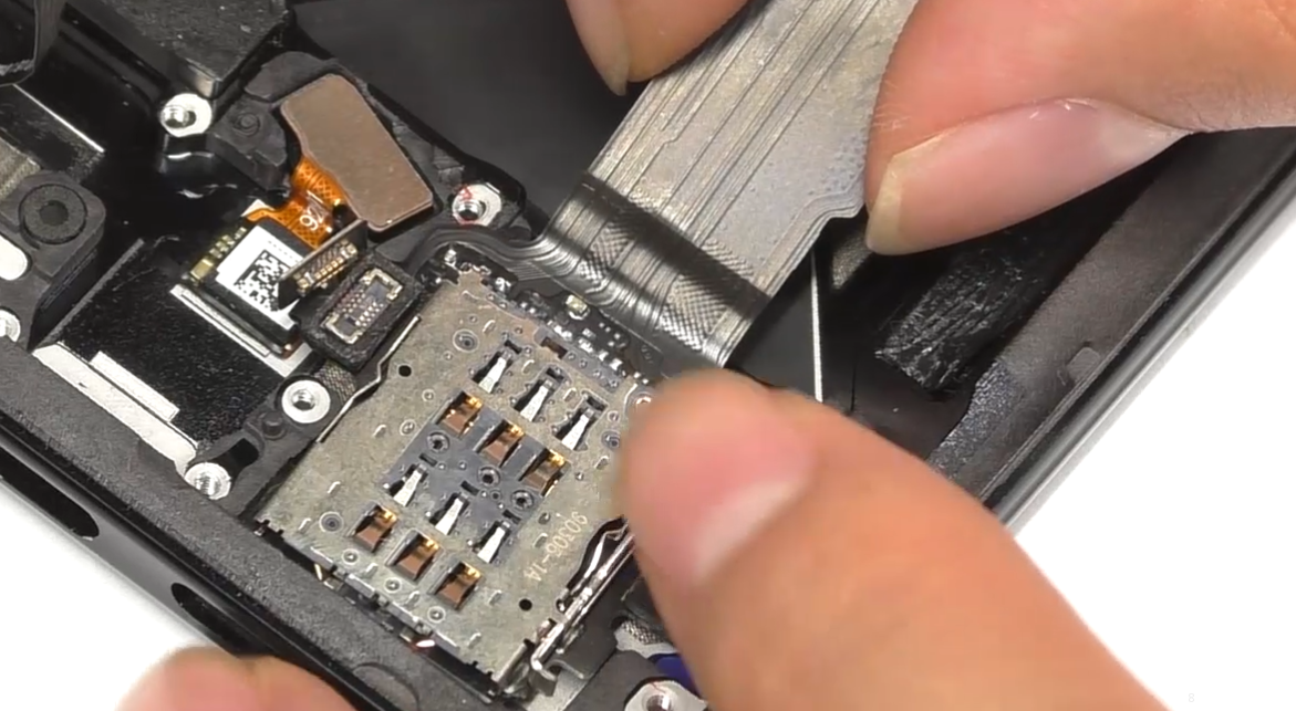 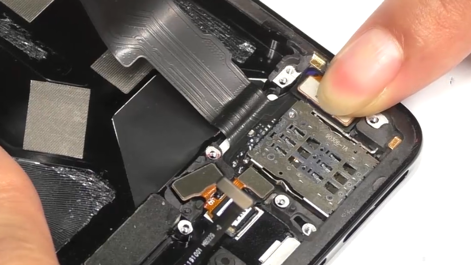 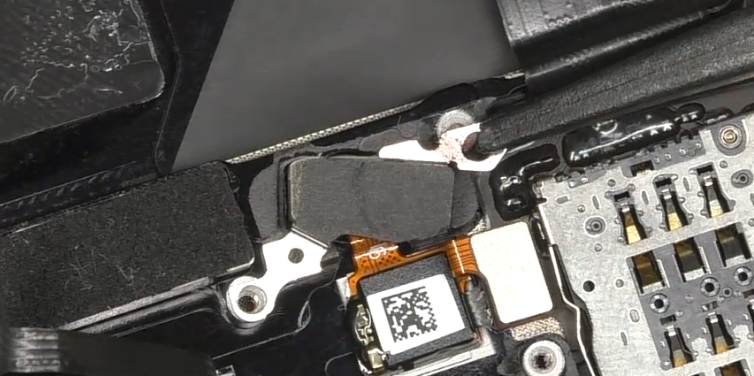 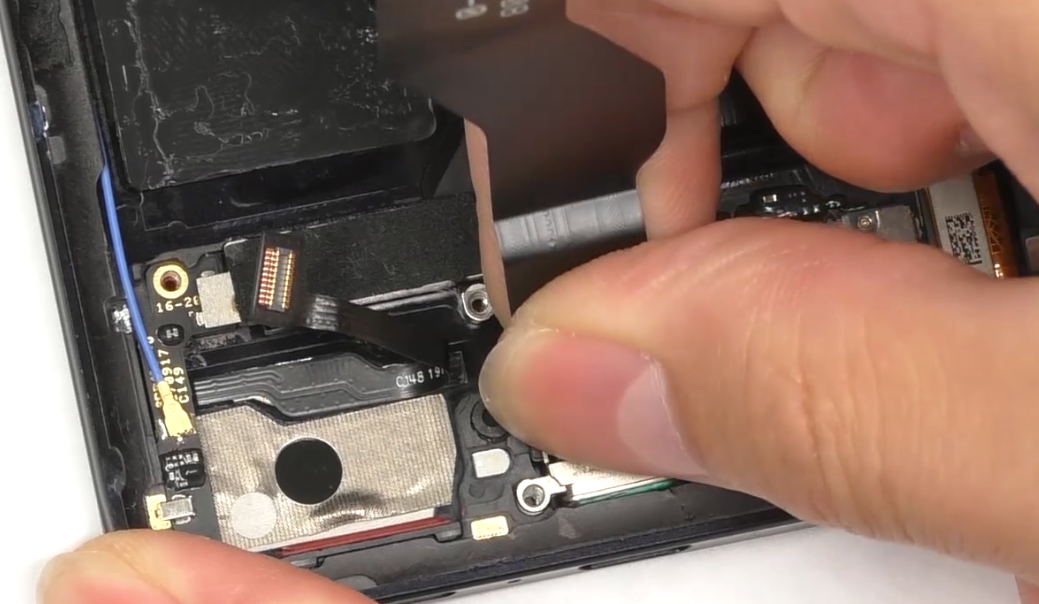 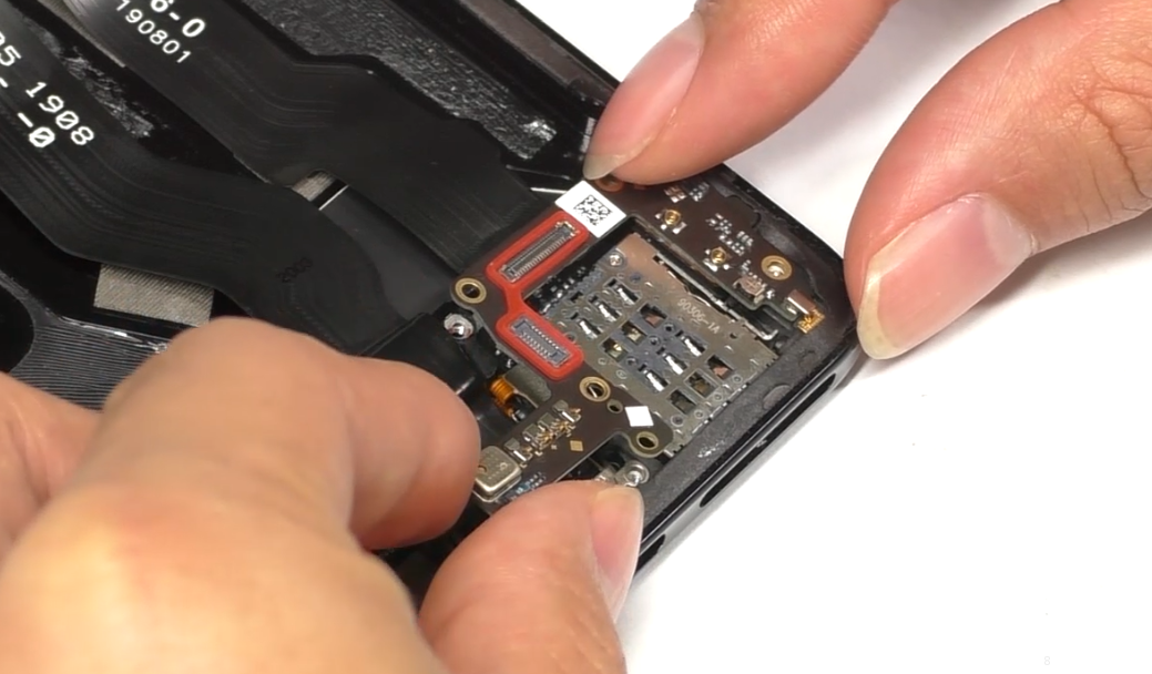 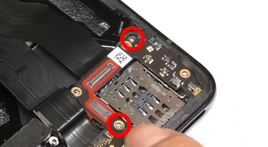 | (1) The screws for the A board (antenna board) are #2(2pcs). |
| 4 | Install RF cable, speaker and apply thermal gel | 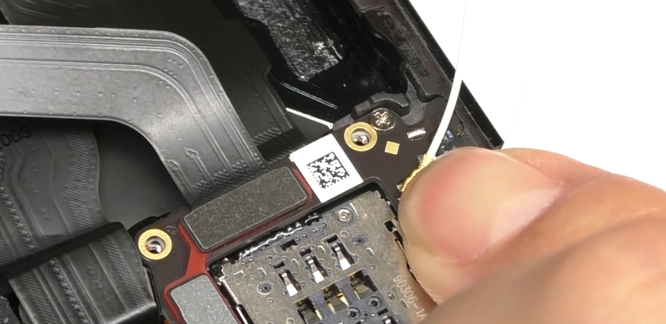 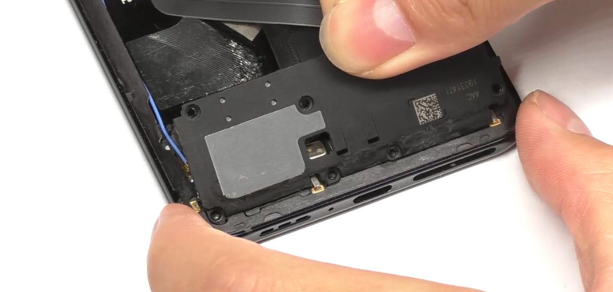 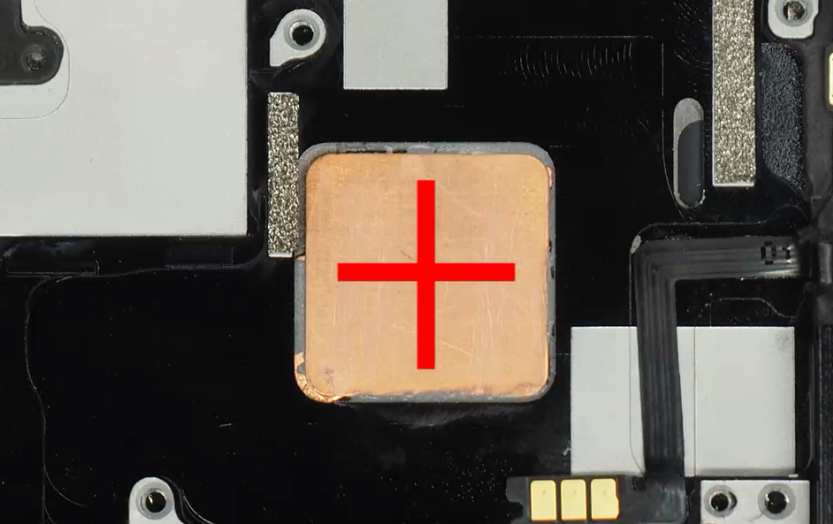 | (1) Note the differences between the RF cables; (2) The screws for the speaker here are #1 (8pcs). (3) Uniformly apply the thermal conductive gel along the red path shown in the figure. |
| 5 | Install the mainboard, the RF cable on the mainboard end | 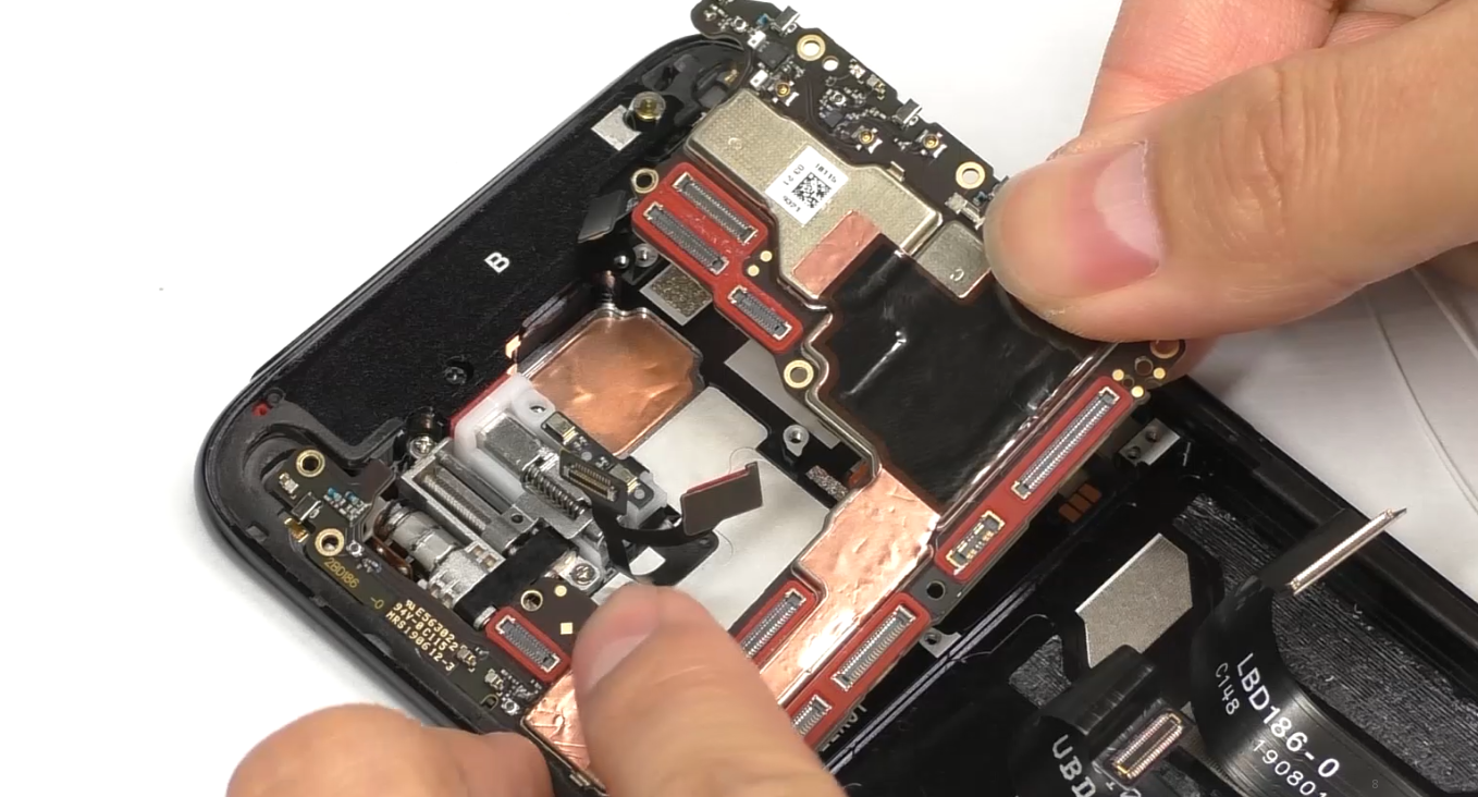 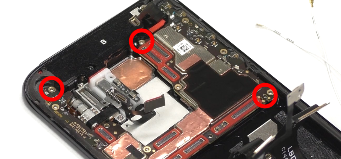 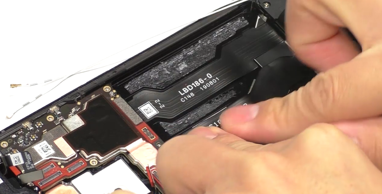 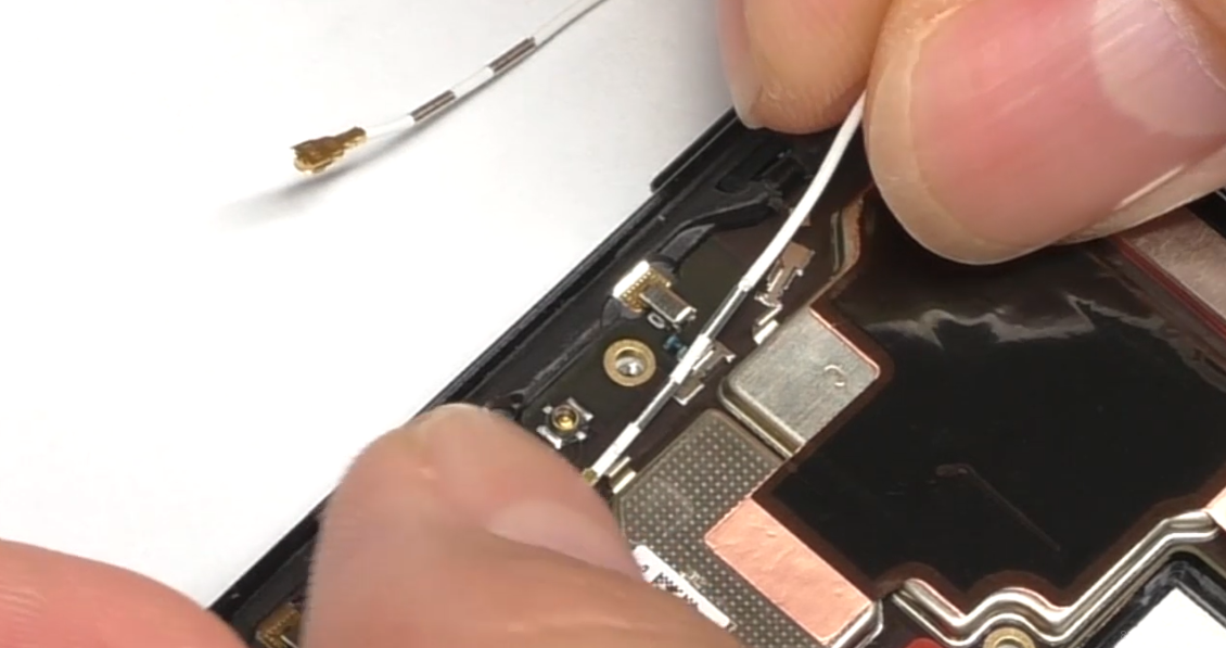 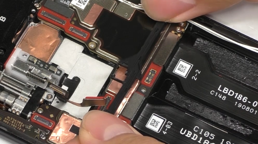 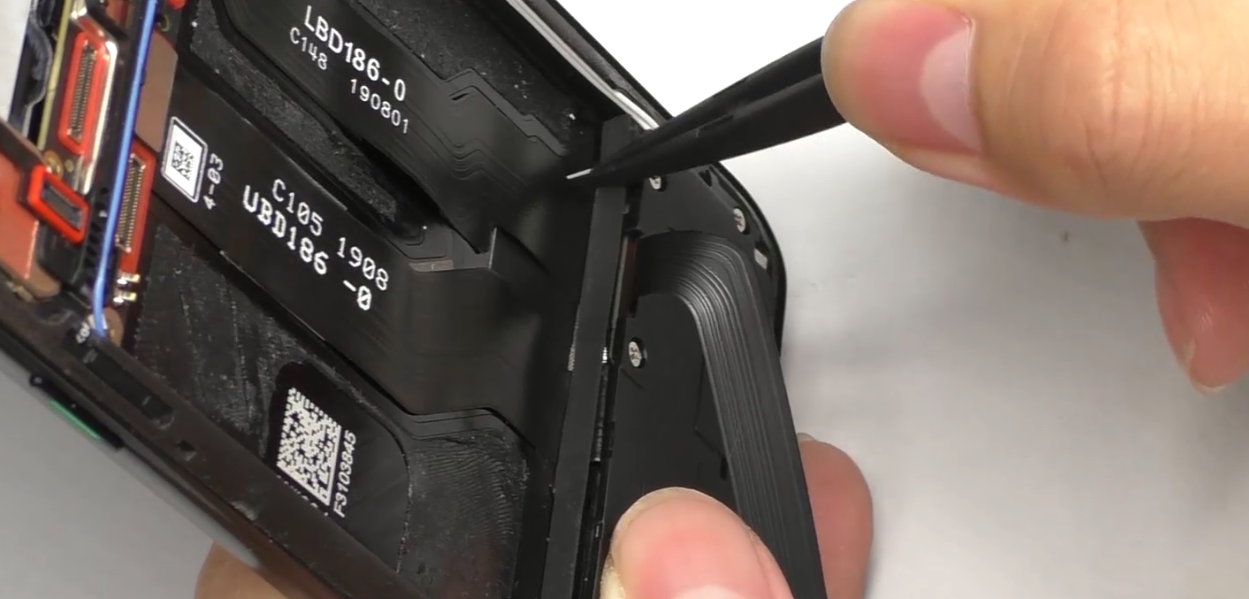 | (1) Install the mainboard from the left side, avoid damage FPC and motor solder joints. (2) The screws for the mainboard are #2 (2pcs); (3) When installing the RF cables, distinguish the position, and insert them into the slot. |
| 6 | Install camera, battery, mainboard board bracket and the battery cover | 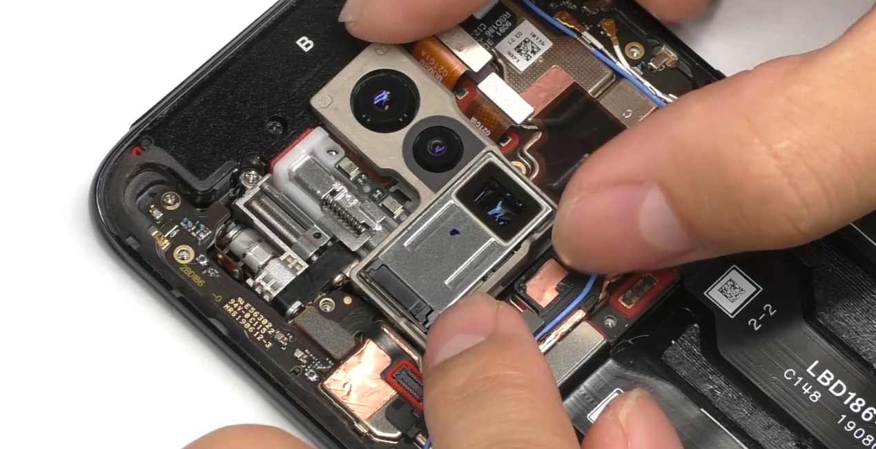 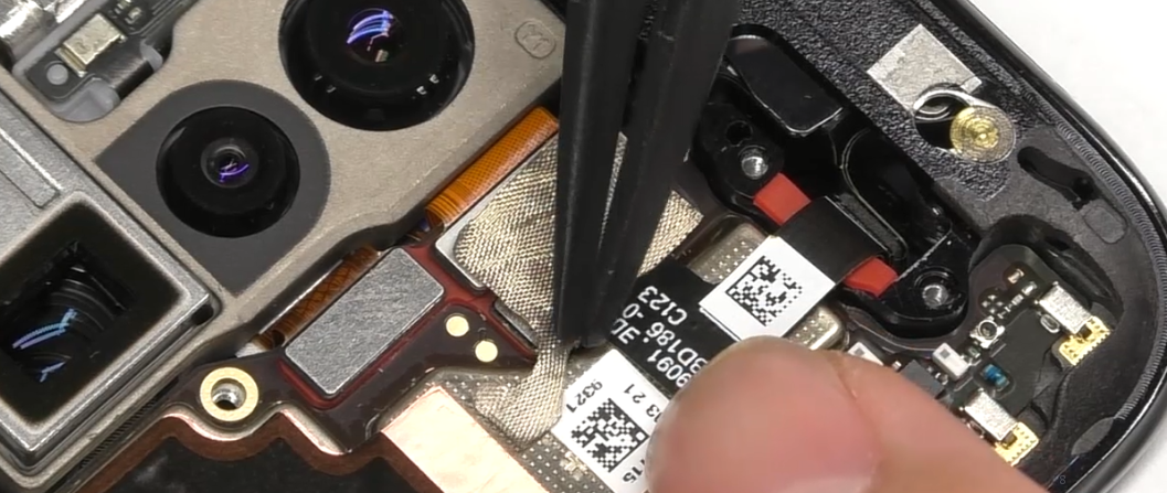 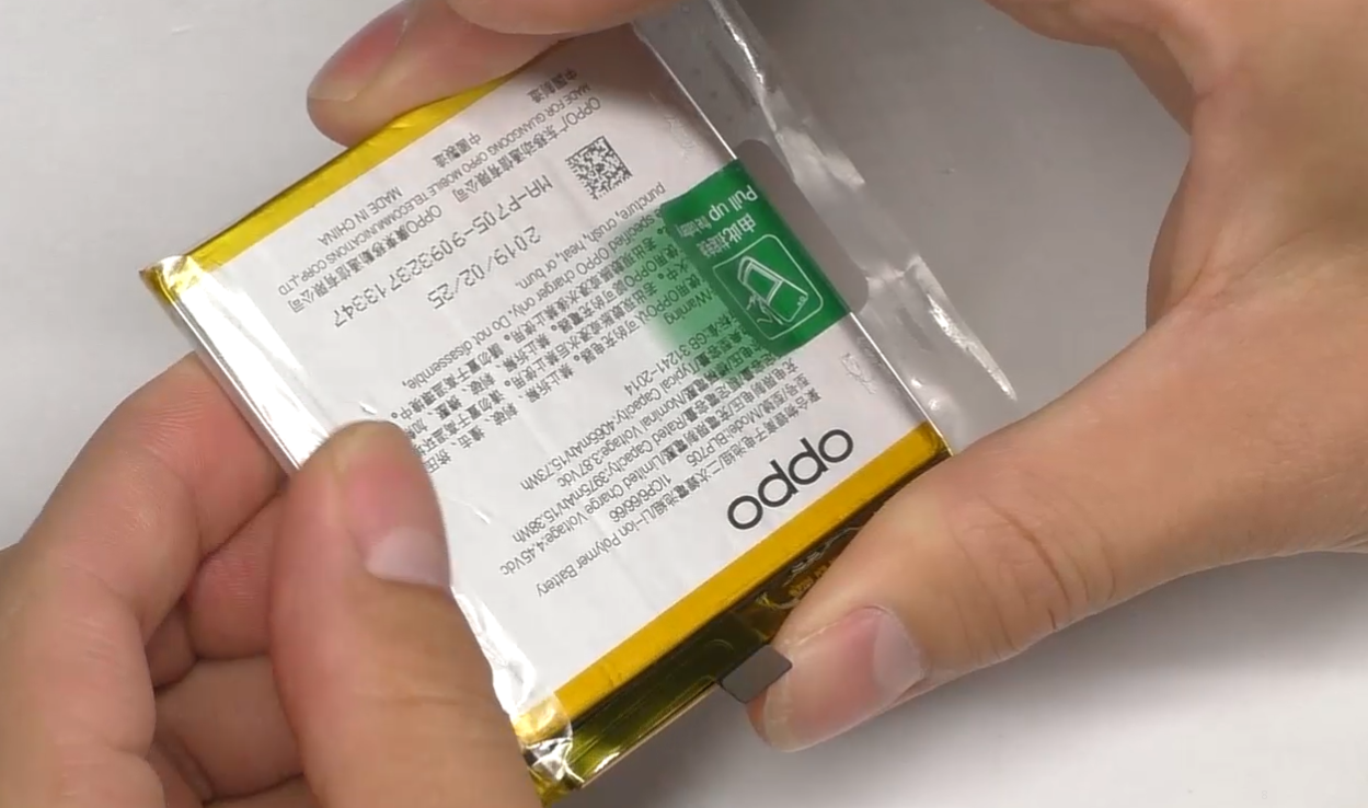 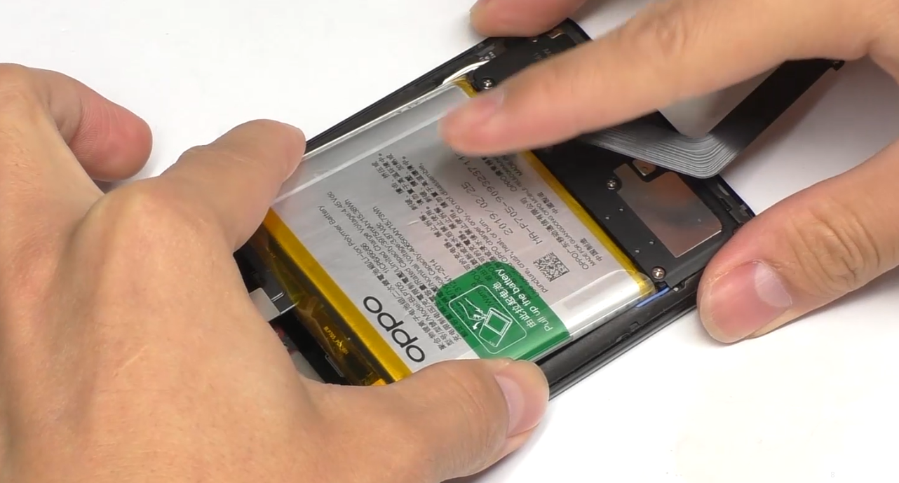 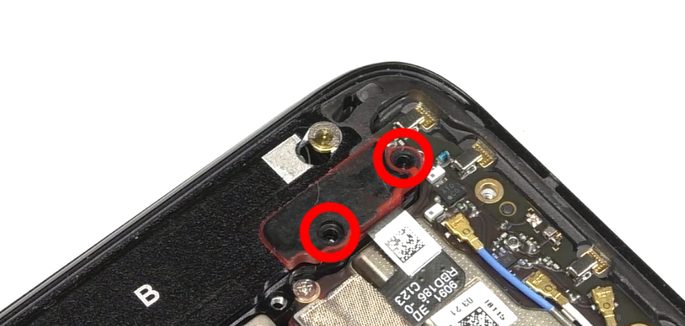 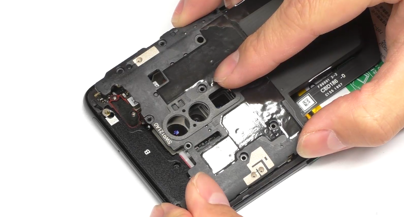 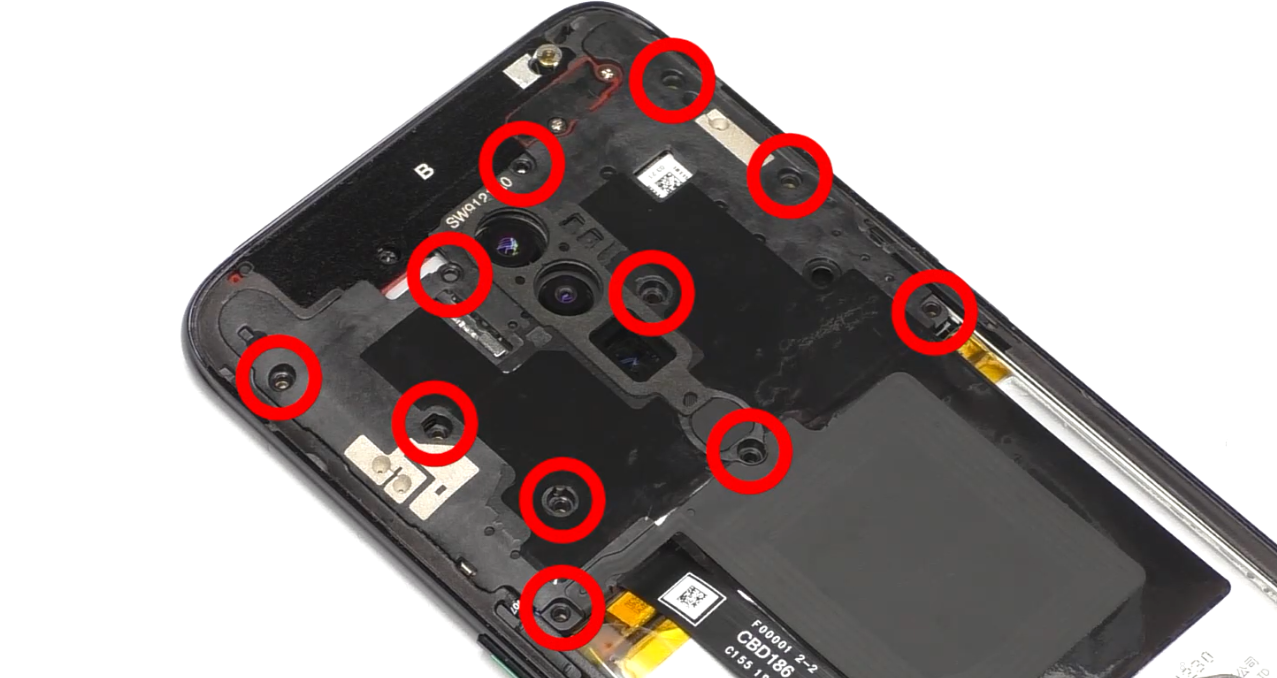 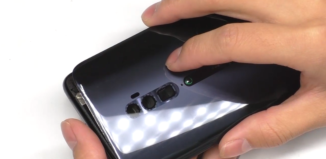 | (1) After installing the camera, attach the camera conductive cloth; (2) It is necessary to replace the new battery easy-tore paper; (3) The screws for the mainboard bracket are #1 (11pcs). |
6. Calibration
6.1 Fingerprint optical calibration
6.1.1 Calibration Scenario
The following fingerprint calibration must be performed after disassembling or replacing any of the main board, fingerprint module, protective film, and screen cover assembly.6.1.2 Calibration Tool
The calibration tool is shown in Figure 6.1.2-1: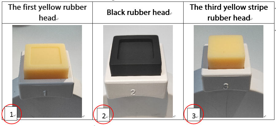
Figure 6.1.2-1
As shown in the Figure 6.1.2-2, the yellow stripe rubber head is with parallel stripes.
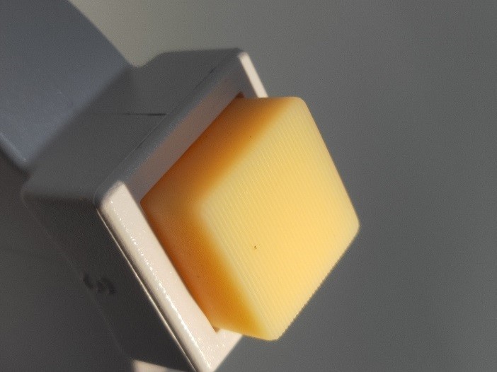
Figure 6.1.2-2
The schematic diagram during measure is shown in Figure 6.1.2-3:
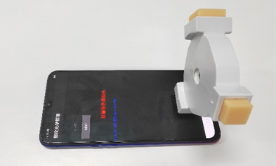
Figure 6.1.2-3
6.1.3 Calibration Method
Calibration path: Enter *#899# in the dial interface>Aftersales Devices Calibration> Enter password “6776” >Infrared Proximity Calibration > Fingerprint calibration,Specific operations refer to calibration page hints:| Operation | 1. Make sure there is no material covering the phone, then press the infrared access calibration button. | 2. Click "START" to start calibration after it jumps into the fingerprint optical calibration, |
|
| Icon | 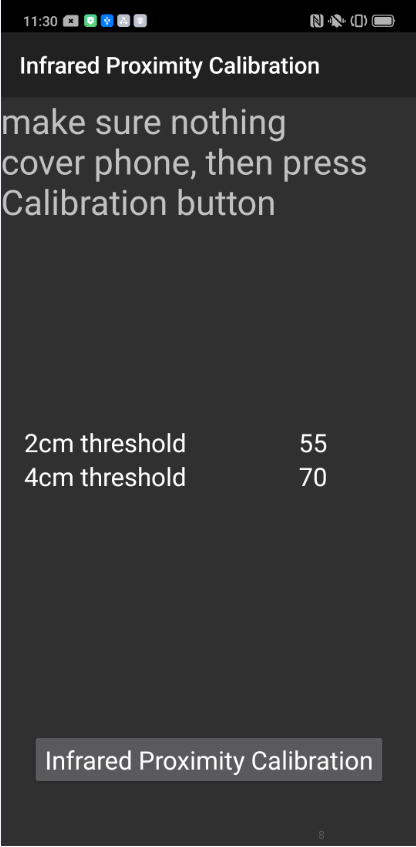 | 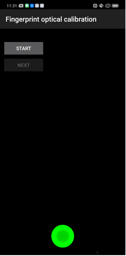 | 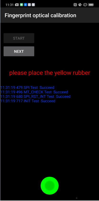 |
| Operation | 4. According to the prompt "please place the black rubber head", put the black rubber on the fingerprint spot area (the groove is facing down), click "NEXT" until the "please place the yellow stripe rubber " prompts to remove the black rubber ; | 5. According to the prompt “Please place the yellow- striped rubber”, put the yellow stripe rubber (striped down) in the spot area, click “NEXT”; | 6. Prompt “Test completed, please reboot”, remove the yellow stripe rubber and complete the test; If the prompt is fail, check if there is a problem with the fingerprint module installation and recalibrate the test. |
| Icon | 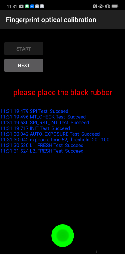 | 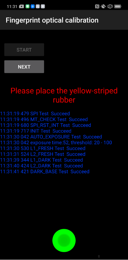 | 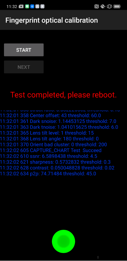 |
Note:
(1) The stripe direction of the yellow stripe rubber should follow the long side of the phone. As shown on the Figure 6.1.3-1.
(2) after the calibration is completed, the phone needs to be restarted.

Figure 6.1.3-1
6.2 Motor Hall Calibrate
6.2.1 Calibration Scenario
If there is a gap in the camera slider, poor smoothness or noises when sliding, first upgrade the phone to the latest software version and then perform Motor Hall calibration for the phone. If the slider is with the fault after Hall calibration, repair the related assembly for the phone.6.2.2 Calibration Method
Step 1: Enter “*#899#” on the dial keypad to enter the engineering mode, then click “Motor Hall Calibration” and enter the password “6776” to enter the Motor Hall calibration interface.Step 2: Confirm the default calibration parameters (Default Value for Reno: near: 40; far:15). After confirming, click “Start Calibrate”; if it displays “PASS” and automatically jump to the next interface, the slider is sound. If the slider is not fully raised or “FAIL” is displayed, the slider is defective.
Step 3: After the Motor Hall calibration test “PASS” and jumps to the “Drive Motor Test”, click the “Start Test”. If “PASS” is displayed, the next interface will be automatically jumped. If the slider is not fully raised or “FAIL” is displayed. ", then the hardware is defective.
Note: Try several times of Motor Hall calibration to confirm if the hardware is defective.
7. Function Test
7.1 Test Path
Dialing Interface>Enter*#899#>Enter automatic test; The "Confirm" dialog box will pop up after the test complete, if there is no problem choose “Pass”, otherwise choose “Fail”.7.2 Test Requirements
| No. | Test Items | Test Requirements |
|---|---|---|
| 1 | LCD Test | Observe the red, green, blue, white, black, gray, grayscale and color interface successively; If there are black spots, bright spots and other anomalies, the function is sound; |
| 2 | Vibration Test | Get ear close to check the vibration from the motor for 3 seconds. If the motor vibrates normally(No noises or weak vibration), the function is sound; |
| 3 | Touch Screen Auto Test | If the interface shows “PASS” and jumps to the next test, the function is sound; |
| 4 | Front Camera Preview | Align the front camera with a white surface and a black surface. If there is no black dot, black line or blurred screen on the screen after aligning the white surface, and there is no bright spot on the screen after aligning the black surface, the camera is sound; |
| 5 | Rear camera preview | Align the rear camera with a white surface, a black surface, and a surface with text. If there is no black dot, black line or blurred screen on the screen after aligning the white surface, there is no bright spot on the screen after aligning the black surface, white point or blurred screen, the camera is sound; |
| 6 | Second rear camera preview | Align the rear camera with a white surface, a black surface, and a surface with text. If there is no black dot, black line or blurred screen on the screen after aligning the white surface, there is no bright spot on the screen after aligning the black surface, white point or blurred screen, the camera is sound; |
| 7 | Third rear camera | Align the rear camera with a white surface, a black surface, and a surface with text. If there is no black dot, black line or blurred screen on the screen after aligning the white surface, there is no bright spot on the screen after aligning the black surface, white point or blurred screen, the camera is sound; |
| 8 | Echo test | Testing Main MIC: Blow the air to the MIC hole on the bottom of the phone. If the receiver (earphone) sounds, the function of Main MIC is sound; Testing Sub MIC: Blow the air to the sub MIC hole on the top of the phone. If the speaker sounds, the function of Main MIC is sound; |
| 9 | Flashlight Test | Open the flashlight. If it can be opened normally with color deviations, the function is sound; |
| 10 | Charging Test(VOOC) | Use the original OPPO adapter and USB cable to charge. If the interface shows “PASS” and jumps to the next test, the function is sound; |
| 11 | Headset in-out Plug test | Plug in and out the earphone with the OPPO earphone. If the interface shows “PASS” and jumps to the next test, the function is sound; |
| 12 | Sensor Self-test and Calibration | When the phone enters into the Sensor self-calibration interface, the phone must be placed on the desk flatly. Then click the first calibration item. After the test is passed, it will automatically jump to the next test item |
| 13 | Gyroscope Test | Take the mobile phone to draw the "8" word graphic. If the interface shows “PASS” and jumps to the next test, the function is sound; |
| 14 | M-Sensor Test | Shake the phone from the left to the right side. If the interface shows “PASS” and jumps to the next test, the function is sound; |
| 15 | Proximity-sensor Test(100mA) | Use the palm to cover the light sensor hole, and the screen will turn green from black. If the interface shows “PASS” and jumps to the next test, the function is sound; |
| 16 | Proximity-sensor Test(150mA) | Use the palm to cover the light sensor hole, and the screen will turn green from black. If the interface shows “PASS” and jumps to the next test, the function is sound; |
| 17 | Keypad Test | Press the power key and volume key one by one. If keys can be pressed normally and the interface jumps to the next test, the function is sound; |
| 18 | Fingerprint Auto Test | If the interface shows “PASS” and jumps to the next test, the function is sound; |
| 19 | Media test | Click the “20-4K(-3db)signal” to test the sound of the media function for 5s. If there is no silence, weak sound, noises, and breaking sound, the interface shows “PASS” and jumps to the next test, the function is sound; |
| 20 | Call test | If the phone has been installed with the operator's SIM card, dial the corresponding operator's phone number. If no card is installed, call the 112 to test (Calling the Operator is recommended). If the call can be performed normally and the receiver is without noises or weak sounds, the function is sound; |
| 21 | NFC Test | Close the phone of the rear camera area to the NFC card reader. If the signal light of the card reader changes from red to green with “Beep” sound, the interface shows “PASS” and jumps to the next test, the function is sound |
| 22 | Laser Focus | Align the phone with the black object or interface and move it back and forth. If it shows “PASS”, the function is sound. |
After the above 22 items are tested, they will prompt to the test result interface. If the test PASS, project will show “√”; If the test FAIL, project will show “×” as shown below.
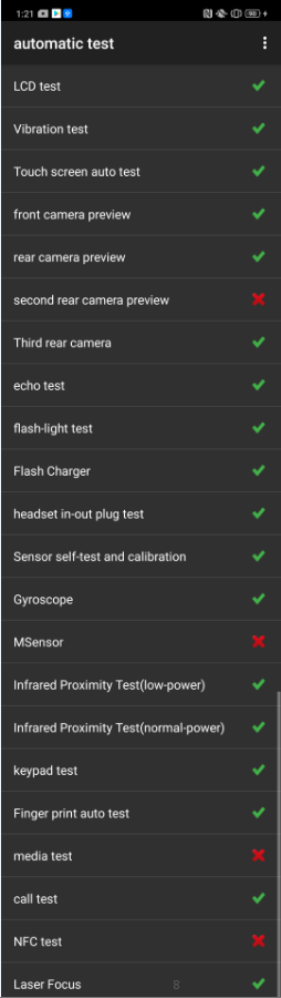
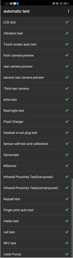
Figure 7-1 Figure 7-2
8. General Cautions
1. Calibration is required after maintenance if there is any replacement of mainboard, display or fingerprint module.
2. After assembly, calibration must be performed before functional test to ensure the proper usage;
3. Some sensory test items may require artificial judgments such as LCD test, vibration test, pre-test, post-test, flash test, echo test, audio test, and call test. Therefore, test judgment requirements must be followed when operate function tests.
4. It is not allowed to press the return key to judge the result in advance if the test items have not been tested.
----Technical Support Team of OPPO Service Dept.