A1K Service Manual -V1
Views: 0 • Likes: 0

Content
1.Guidance
2.General Repair Information
3. Phone Structure Diagram
4. Disassembly Steps
5. Assembly Steps
6. Calibration
7. Function Test
8. General Cautions
1. Guidance
The purpose of this document is only to guide OPPO technicians to carry out maintenance service to OPPO products. The content shall be keep in confidential, only avail be able to OPPO authorized service centers, and cannot be provided to third parties without authorization. Please follow the regulations and the guidance for maintenance service. For any problems, please contact China HQ in time.
1.1 Warnings and Cautions
1.1.1 Warnings
1. Care must be taken on installation in vehicles fitted with electronic engine management systems and ABS (Anti–skid Braking Systems). Under certain fault conditions, emitted RF energy can affect their operation. If necessary, consult the vehicle dealer/manufacturer to determine the immunity of vehicle electronic systems to RF energy.
2. Phones must not be operated in areas likely to contain potentially explosive atmospheres, e.g. petrol stations (service stations), blasting areas etc.
3. Operation of any radio transmitting equipment, including cellular telephones, may interfere with the functionality of inadequately protected medical devices. Consult a physician or the manufacturer of the medical device if you have any questions. Other electronic equipment may also be subject to interference
1.1.2 Cautions
1. Repair services and calibrations must be undertaken by qualified personnel only.
2. Use only approved components as specified in the parts list.
3. Ensure all components, modules screws and insulators are correctly re-fitted after servicing and alignment.
4. Electrostatic discharge is the main cause of damage to sensitive components of electronic products. Service centers must operate in accordance with OPPO's requirements for ESD protection. Ensure all work is carried out at an ESD workstation and that an ESD wristband is worn.
2.General Repair Information
1.Ensure all work is carried out at an ESD workstation and that an ESD wristband is worn before starting maintenance.
2.Wear ESD gloves to avoid oil stains and fingerprints.
3.Use protective films to protect the display, camera, camera lens to prevent dust and scratches.
4.Use a clean cloth, ESD brush and alcohol (Concentration above 95%) for appearance cleaning. Do not use other items (such as an eraser) for cleaning to prevent the protective layer from being scratched, which may lead to oxidation and corrosion.
5.Faulty welded mechanical parts (except shield cover and shield frame parts) can only be replaced and not repairable.
6.Use accessories provided by OPPO.
7.Check the contacts or solder joints of devices that may cause simple faults (e.g. soldered interfaces or switches). Re-weld if necessary (only for service centers where lead-free soldering is available) and clean the flux remaining after soldering.
8.Use the equipment provided by OPPO to test the phone (e.g. When the charging function of the device is abnormal, do use the original OPPO adapter to test to ensure the accuracy of the test results).
9.Fill in the fault phenomenon code and fault reason code according to the actual situation, and accurately enter the replacement material code in the CRM system (Refer to the Smart Phone Fault Reason Matching Code List if necessary).
10.For more information about products, please visit the company FTP server: ftp://ftpex.oppo.com:919/
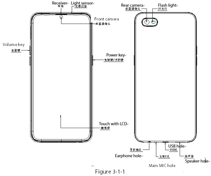
3. Phone Structure Diagram
3.1 Product Appearance
As shown in Figure 3-1-1
3.2 Phone Structure Explosive View
As shown in Figure 3-2-1
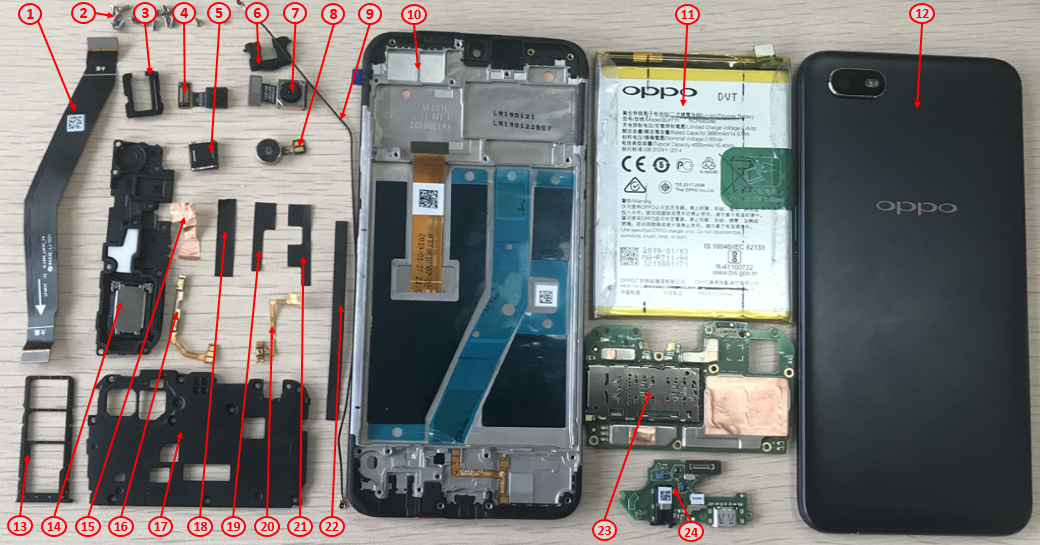
Figure 3-2-1
3.3 Corresponding Material Table:
| SN | Material | SPEC. | Unit | QTY |
|---|---|---|---|---|
| 1 | Semi-finished FPC | 18540-MAIN FPC-patch_HQ-A1 WINTER HQ | PCS | 1 |
| 2 | Non-self-tapping screw | M1.4×3.5mm Nylok silver HQ | PCS | 20 |
| 3 | Sealed silicone case for Headphone seat | 18540 Black HQ | PCS | 1 |
| 4 | Front Camera | Samsung 3264*2448 8.5*8.5*5.2 5P BTB TA8S1EB HQ | PCS | 1 |
| 5 | Receiver | 50mW 28Ω 0908*2.05 HQ | PCS | 1 |
| 6 | Sealed silicone case USB seat | 18540 Black HQ | PCS | 1 |
| 7 | Rear Camera | Samsung 3264*2448 8.5*8.5*5.2 5P BTB TA8S1EB HQ | PCS | 1 |
| 8 | Vibration motor | 14.82*8*3.2 3V 30Ω±15% 10.82mm HQ | PCS | 1 |
| 9 | RF Connection cable | 0.3Ω 171.04mm 818014303 HQ | PCS | 1 |
| 10 | Display assembly | CPH1923 black/red (for after-sales) | PCS | 1 |
| 11 | Battery | @ 3890mAh 3.85V 0.7C BLP711 416286 NA I927 | PCS | 1 |
| 12 | Battery cover assembly | CPH1923 red (for after-sales) | SET | 1 |
| 13 | SIM card holder | 18540 Black HQ | PCS | 1 |
| 14 | Speaker | 1W 8Ω 17*10.85*2.15 HQ | PCS | 1 |
| 15 | Conductive copper foil for the front camera | 18540 Single-sided adhesive HQ | PCS | 1 |
| 16 | Semi-finished FPC | 18540-V-patch_HQ-A1 WINTER HQ | PCS | 1 |
| 17 | Mainboard bracket | 18540 Black with cushion HQ | PCS | 1 |
| 18 | Upper cover BOTTOM surface waterproof PET film | 18540 Single-sided adhesive HQ | PCS | 1 |
| 19 | Power key PET film | 18540 Single-sided adhesive HQ | PCS | 1 |
| 20 | Semi-finished FPC | 18540-P -patch_HQ-A1 WINTER HQ | PCS | 1 |
| 21 | Volume key PET film | 18540 Single-sided adhesive HQ | PCS | 1 |
| 22 | Battery bottom cushion | 18540 Single-sided adhesive HQ | PCS | 1 |
| 23 | Semi-finished PBC | Semi-finished PBC | PCS | 1 |
| 24 | Semi-finished PBC | 18540_AL1891C(A)-V0.4 WINTER HQ | PCS | 1 |
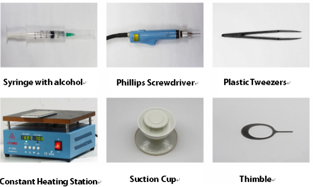
4. Disassembly Steps
4.1 Disassembly Tools
4.2 Preparation
1. The phone must be powered off before disassembly.
2. Way to Power Off:
System Power Off: Press the power key then slide to power off.
Forced Power Off: Long press the volume “+” key and power key for about 8 seconds until the display is off.
4.3 Disassembly Steps
| Step | Content | Figure | Cautions |
|---|---|---|---|
| 1 | Disassemble the battery cover | 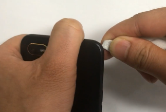 |
|
| 2 | Disassemble the mainboard bracket | 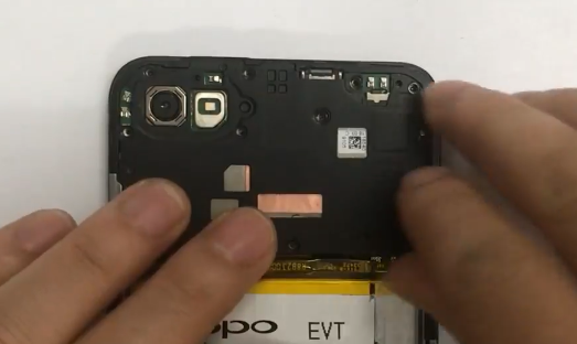 |
|
| 3 | Disassemble the battery | 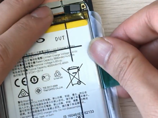 |
|
| 4 | Disassemble the front camera and rear cameras | 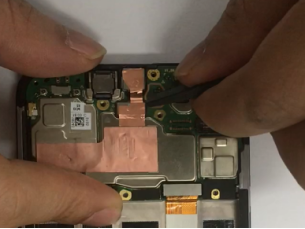 |
|
| 5 | Disassemble Display FPC, RF Connection Cable , and Mainboard | 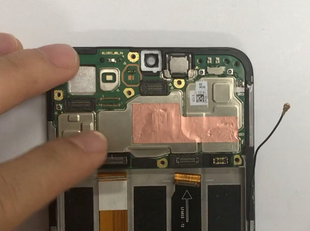 |
|
| 6 | Disassemble the speaker box and the Antenna board | 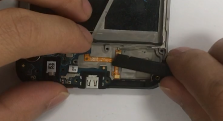 |
|
| 7 | Disassemble the Receiver ,Power key FPC ,and volume key FPC | 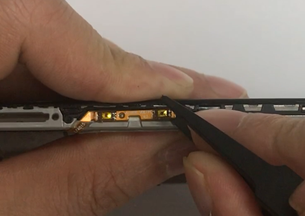 |
|
| 8 | Disassemble the battery bottom cushion, main FPC,and the motor | 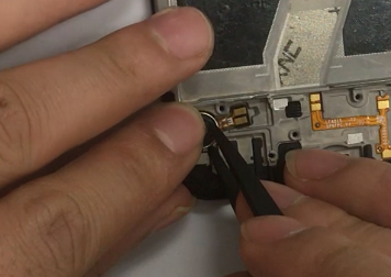 |
5. Assembly Steps
5.1 Bill of Must-Be-Replaced Materials
| No. | Material | Code | PCS |
|---|---|---|---|
| 1 | Non-self-tapping screw | 4210672 | PCS |
| 2 | Battery Easy-tore Paper | 4876448 | PCS |
| 3 | Battery extracting sticker | 5181711 | PCS |
| 4 | Decorative Piece Tape for Rear Camera | 4876862 | PCS |
| Step | Content | Figure | Cautions |
|---|---|---|---|
| 1 | Assemble the receiver ,motor ,power key FPC, and volume key FPC | 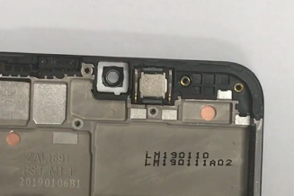 |
|
| 2 | Assemble mainboard ,front camera and rear camera lens |  |
|
| 3 | Assemble USB seat, sealed silicone case , Headphone seat sealed silicone case, antenna board , and main FPC | 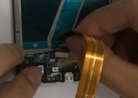 |
|
| 4 | Assembly speaker , Battery bottom cushion, Non-self-tapping screws, and the battery | 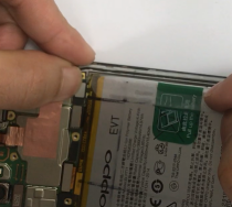 |
|
| 5 | Assemble Mainboard bracket, screws , PET sheet for side keys , PET sheet for the mainboard assembly | 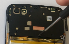 |
|
| 6 | Assemble the battery cover | 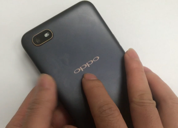 |
6. Calibration
NA
7. Function Test
7.1 Test Path
Dialing Interface>Enter*#899#>Enter automatic test; The "Confirm" dialog box will pop up after the test complete, if there is no problem choose “Pass”, otherwise choose “Fail”.
7.2 Test Requirements
| No. | Test Items | Test Requirements |
|---|---|---|
| 1 | LCD Test | Observe the red, green, blue, white, black, gray, grayscale and color interface successively; If there are black spots, bright spots and other anomalies, the function is sound; |
| 2 | Vibration Test | Get ear close to check the vibration from the motor for 3 seconds. If the motor vibrates normally(No noises or weak vibration), the function is sound; |
| 3 | Touch Screen Auto Test | If the interface shows “PASS” and jumps to the next test, the function is sound; |
| 4 | Front Camera Preview | Align the front camera with a white surface and a black surface. If there is no black dot, black line or blurred screen on the screen after aligning the white surface, and there is no bright spot on the screen after aligning the black surface, the camera is sound; |
| 5 | Rear camera preview | Align the rear camera with a white surface, a black surface, and a surface with text. If there is no black dot, black line or blurred screen on the screen after aligning the white surface, there is no bright spot on the screen after aligning the black surface, white point or blurred screen, the camera is sound; |
| 6 | Echo test | Testing Main MIC: Blow the air to the MIC hole on the bottom of the phone. If the receiver (earphone) sounds, the function of Main MIC is sound; Testing Sub MIC: Blow the air to the sub MIC hole on the top of the phone. If the speaker sounds, the function of Main MIC is sound; |
| 7 | Flashlight Test | Open the flashlight. If it can be opened normally with color deviations, the function is sound; |
| 8 | Charging Test | Use the original OPPO adapter and USB cable to charge. If the interface shows “PASS” and jumps to the next test, the function is sound; |
| 9 | Headset in-out Plug test | Plug in and out the earphone with the OPPO earphone. If the interface shows “PASS” and jumps to the next test, the function is sound; |
| 10 | Sensor Self-test and Calibration | When the phone enters into the Sensor self-calibration interface, the phone must be placed on the desk flatly. Then click the first calibration item. After the test is passed, it will automatically jump to the next test item |
| 11 | M-Sensor Test | Shake the phone from the left to the right side. If the interface shows “PASS” and jumps to the next test, the function is sound; |
| 12 | Proximity-sensor Test | Use the palm to cover the light sensor hole, and the screen will turn green from black. If the interface shows “PASS” and jumps to the next test, the function is sound; |
| 13 | Keypad Test | Press the power key and volume key one by one. If keys can be pressed normally and the interface jumps to the next test, the function is sound; |
| 14 | Media test | Click the “20-4K(-3db)signal” to test the sound of the media function for 5s. If there is no silence, weak sound, noises, and breaking sound, the interface shows “PASS” and jumps to the next test, the function is sound; |
| 15 | Call test | If the phone has been installed with the operator's SIM card, dial the corresponding operator's phone number. If no card is installed, call the 112 to test (Calling the Operator is recommended). If the call can be performed normally and the receiver is without noises or weak sounds, the function is sound; |
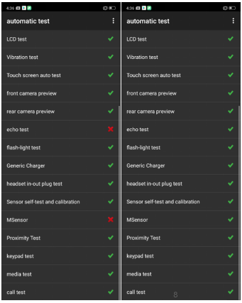
Figure 7-1 Figure 7-2
8. General Cautions
NA
----Technical Support Team of OPPO Service Dept.