Reno2 Service Manual
Views: 0 • Likes: 0

Content
1. Guidance
2. General Repair Information
3. Product Overview
4. Disassembly steps
5. Assembly Step
6. Calibration
7. Function test
8. Cautions
1. Guidance
The purpose of this document is used to guide OPPO maintenance engineers to carry out service to OPPO products, and the content shall be keep in confidential. This Service Manual is to be used only by authorized OPPO maintenance service centers, not be provided to third parties for use without authorization. Please follow the regulations and follow the guidance for maintenance service, please contact HQ if any questions.
1.1 warnings and Cautions:
1.1.1 Warnings
1. Service centers may be required to install the handset's vehicle-mounted system in vehicles. Under certain fault conditions, the handset's RF signals may affect the operation of the vehicles' electric power management systems and anti–skid braking systems (ABS). If necessary, consult the vehicle dealer/manufacturer to determine the immunity of vehicle electronic systems to RF energy.
2. The handset must not be operated in areas likely to contain potentially explosive atmospheres, such as petrol stations, gas stations and blasting areas.
3. Operation of any radio transmitting equipment, including handsets, may interfere with the functionality of the medical devices protected by industrial mechanisms. Consult the manufacturer of the medical device if necessary. Other electronic equipment may also be subject to interference.
1.1.2 Cautions
1. Maintenance and calibration must be undertaken by qualified technicians only.
2. Use only the materials listed in the BOM for maintenance services.
3. All parts are assembled correctly as required.
4. Electrostatic discharge can easily damage the sensitive components of electronic products. Service centers must follow with OPPO's requirements for electrostatic protection. All the operations must be on an ESD maintenance table and worn with an ESD ring.
2. General Repair Information
1. Before starting the maintenance, please enter the ESD area and wear the ESD ring.
2. ESD gloves are recommended to avoid oil stains and fingerprints.
3. Use protective film to protect the display screen, camera, and camera lenses from dust and scratches.
4. It is necessary to use dust-free cloth, ESD brush and alcohol (concentration above 95%) for appearance cleaning. Do not use other items for cleaning (like eraser) to prevent the protective layer on the scratched surface from oxidizing and corroding.
5. It can only be replaced instead of repair if the welded mechanical parts (except the shield cover and shield frame parts) fail.
6. Repairs must be made using the accessories supplied by OPPO.
7. Check the contacts or solder joints of devices that may cause simple faults (e.g. soldered connectors or switches) and re-solder them if necessary (only repair centers that can conduct lead-free soldering) and clean the residual flux after welding.
8. You must use the equipment provided by OPPO to test whether the mobile phone is normal. For example, if the customer feedback charging malfunction, please use the original adapter of OPPO to test to ensure the accuracy of test results.
9. When recording the fault code in the after-sales system, fill in the fault phenomenon code and fault reason code according to the actual situation, and accurately record the replacement accessory code (refer to " Smart Phone Fault Reason Code List " if necessary.
10. If you want to know more information about this product, please visit the FTP service: ftp://ftpex.oppo.com:919/
3. Product Overview
3.1 Product Appearance:
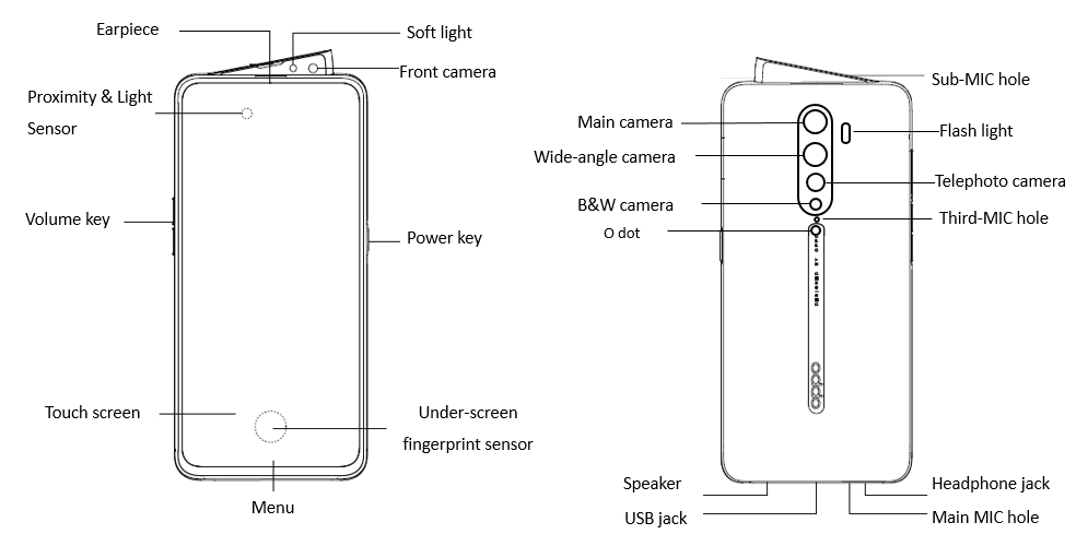
Figue3.1.1
3.2 Exploded View of Phone's Structure:
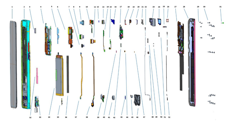
3.3 Exploded map corresponding material table:
| NO | Material Name | Picture | Specifications | Quantity | Unit |
|---|---|---|---|---|---|
| 1 | OLED |  |
Screen | 1 | PCS |
| 2 | Top cover | 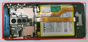 |
1 | PCS | |
| 3 | Proximity sensors silicone sets |
 |
AE001 black | 1 | PCS |
| 4 | Mainboard | 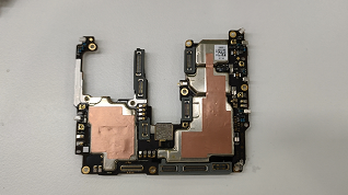 |
2AE002-0 19331 | 1 | PCS |
| 5 | Rear camera conductive cloth |
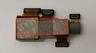 |
AE001 | 1 | PCS |
| 6 | Main camera | 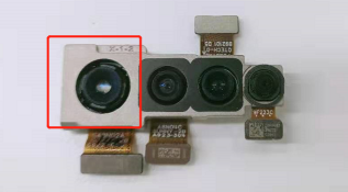 |
IMX586 48M 39.3mm*14.5mm*6.82mm 6P BTB S48N02A | 1 | PCS |
| 7 | Wide-angle camera | 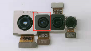 |
IMX319 8M 8*9.2*6.07 5P BTB A8N04C | 1 | PCS |
| 8 | Telephoto camera | 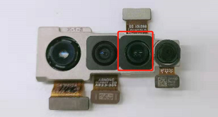 |
S5K3M5SX04 13.0M 8.80×7.70×6.46 5P BTB F3M5YAE | 1 | PCS |
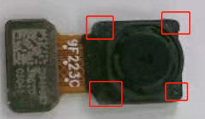
| 9 | B&W camera | 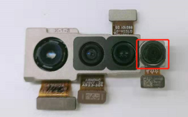 |
GC02M0 2.0M 5.7×6.0×3.16 3P BTB 9F223C | 1 | PCS |
| 10 | R board | Combined in front camera | RAE002-0 | 1 | PCS |
| 11 | Front camera | 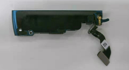 |
S5K3M5SX04 13.0M 8.80×7.70×6.46 5P BTB F3M5YAE | 1 | PCS |
| 12 | Front camera FPC bent foam |
Combined in front camera | AD067 black | 1 | PCS |
| 13 | Receiver | Combined in front camera | 50mW 32Ω 7×10×2.5 A | 1 | PCS |
| 14 | Flash FPC | Combined in front camera | FAE002-0 | 1 | PCS |
| 15 | N board | Combined in front camera | NAE002-0 | 1 | PCS |
| 16 | Front camera lens | 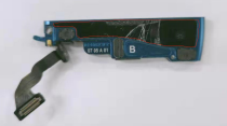 |
AE001 black glass GG5 with adhesive | 1 | PCS |
| 17 | Transmission case | 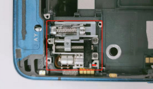 |
AE001 Stainless steel | 1 | PCS |
| 18 | Front Flash FPC Fixed Bracket | Combined in front camera | AE001 | 1 | PCS |
| 19 | Deputy MIC stent | Combined in front camera | AE001 with adhesive | 1 | PCS |
| 20 | Front Camera BTB Bracket | Combined in front camera | AE001 Stainless steel | 1 | PCS |
| 21 | Small and Medium Frame Pressure Plate Support |
Combined in front camera | AE001 Stainless steel | 1 | PCS |
| 22 | RF cable | 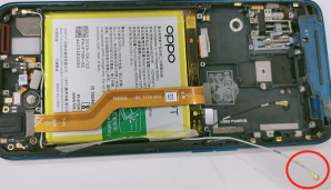 |
50Ω 192.5mm 818015856 | 1 | PCS |
| 23 | Front camera | 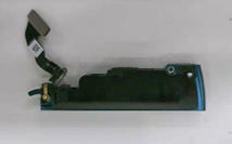 |
CPH1907(19331) | 1 | PCS |
| 24 | Small and Medium Frame Decorative Pieces |
 |
AE001 Stainless steel | 1 | PCS |
| 25 | Connecting rod sealing ring |
 |
AE001 | 1 | PCS |
| 26 | R FPC protection silicone sleeve |
Combined in front camera | AE001 grey | 1 | PCS |
| 27 | Mainboard bracket | 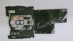 |
AE001 with antenna | 1 | PCS |
| 28 | Backcover |  |
AE001 glass with padding | 1 | PCS |
| 29 | screw | 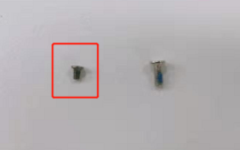 |
CM 1.2×1.8 black nickel(head of diameter 2.0 head thickness 0.3)locking | 5 | PCS |
| 30 | screw | 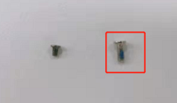 |
CM 1.4×3.5 white nikel(head diameter 2.5 head thickness 0.4) locking 2# | 20 | PCS |
| 31 | Axis A | 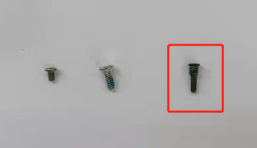 |
AD067 black Stainless steel | 1 | PCS |
| 32 | LCM through-hole PET sheet | 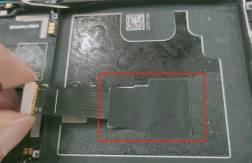 |
AE001 | 1 | PCS |
| 33 | Antenna board | 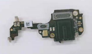 |
AAE002-0 19331 | 1 | PCS |
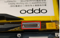
| 34 | Battery | 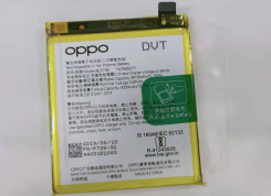 |
@ 3915mAh 3.87V 1.5C BLP735 516270 FA I724 | 1 | PCS |
| 35 | MIMO board | 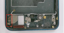 |
6AE002-0-19031 | 1 | PCS |
| 36 | Battery bin RF connection wire cushions |
 |
AE001 PORON single-sided adhesive | 1 | PCS |
| 37 | C-board | 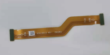 |
CAE002-0- 19031 | 1 | PCS |
| 38 | U-board | 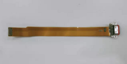 |
UAE002-SB-patch 19031 | 1 | PCS |
| 39 | Fingerprint sensor | 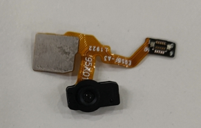 |
GW9558 8.54*3.88*4.26 BTB AE002 B731 UD black | 1 | PCS |
| 40 | Test point PET 3 | 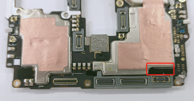 |
AE001 single-sided adhesive | 1 | PCS |
| 41 | Vibration motor | 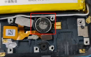 |
Φ8×3.0 3V 32(DM) | 1 | PCS |
| 42 | 2M Camera sealing foam | 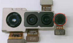 |
AE001 single-sided adhesive | 1 | PCS |
| 43 | Vibration motor foam | 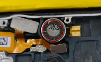 |
AE001 single-sided adhesive | 1 | PCS |
| 44 | Test point PET 1 | 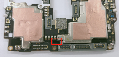 |
AE001 single-sided adhesive | 1 | PCS |
| 45 | Fingerprint bracket | 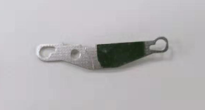 |
AE001 Stainless steel | 1 | PCS |
| 46 | Speaker | 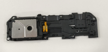 |
1W 7Ω 67*19.7*5.07 BOX A | 1 | PCS |
| 47 | Test point PET 2 | 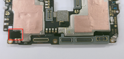 |
AE001 single-sided adhesive | 1 | PCS |
| 48 | LCM BTB waterproof silicone sets |
 |
AE001 grey | 1 | PCS |
| 49 | Rear sub-photographing top double-sided adhesive 1 |
 |
AE001 black | 1 | PCS |
| 50 | Rear sub-photographing top double-sided adhesive 2 |
 |
AE001 black | 1 | PCS |
| 51 | Rear sub-photographing top double-sided adhesive 1 |
 |
AE001 black | 1 | PCS |
| 52 | RF cable | 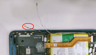 |
50Ω 123.5mm 818015855 | 1 | PCS |
4. Disassembly Steps
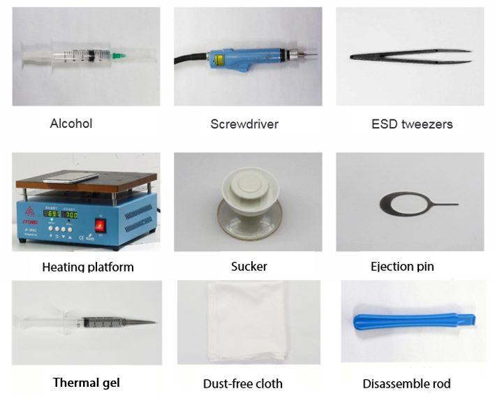
4.1 Disassembly tools required as shown below:
4.2 Preparation
1. The phone must be shut down with the power option before disassembling.
2. Way to Shut Down: Press the power button then slide to power off.( The forced shutdown method is long press the volume + button and power button for about 8 seconds until the display is off)
4.3 Disassembly Steps
| Steps | Details | Picture | Cautions |
|---|---|---|---|
| 1 | Remove the battery cover | 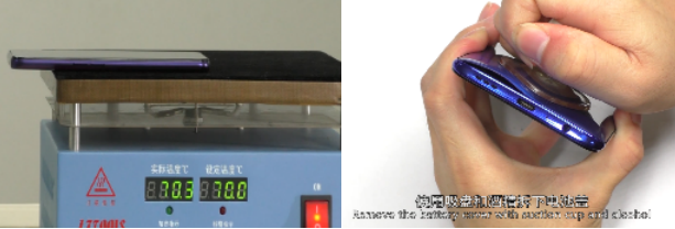 |
1. Place the battery cover face down and heat it at 75 c for 2-4min. 2. It needs to be removed from the USB side. Be careful not to destroy the fingerprint FPC |
| 2 | Remove the mainboard bracket and speaker | 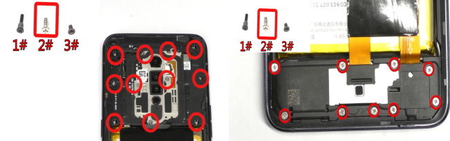 |
/ |
| 3 | Remove C-board and U-board | 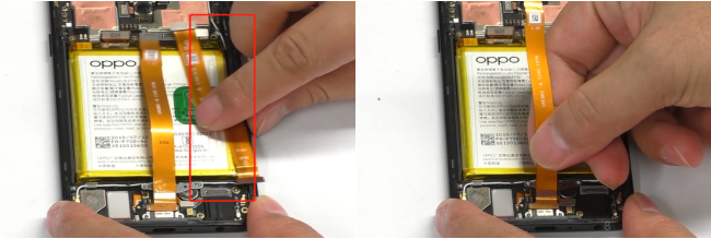 |
/ |
| 4 | Remove the battery | 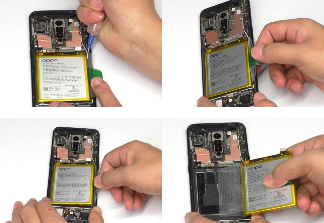 |
1.Be careful not to deform the battery 2.Check for puncture, indentation, leakage and other defects after removing the battery |
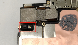
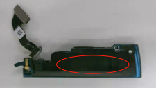
| 5 | Remove the mainboard and rear camera | 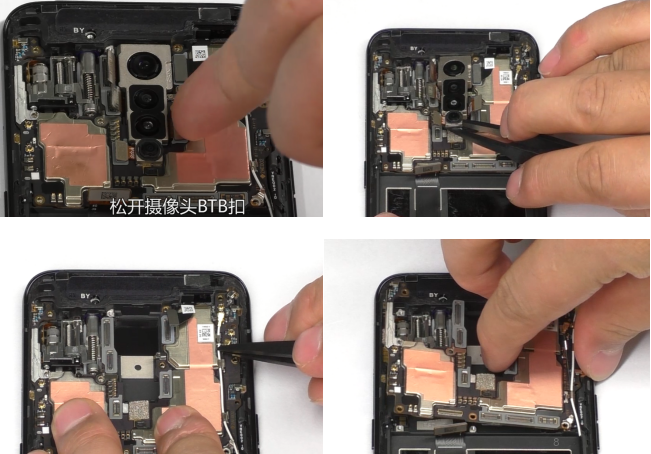 |
Be careful not to damage the RF socket on the motherboard .The BTB buckle must be pulled up vertically to prevent damage to the socket |
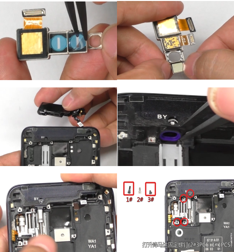
| 6 | Remove the front camera | 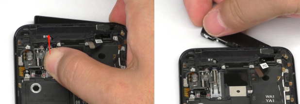 |
Be careful not to destroy the fingerprint FPC |
| 7 | Remove the lifting motor | 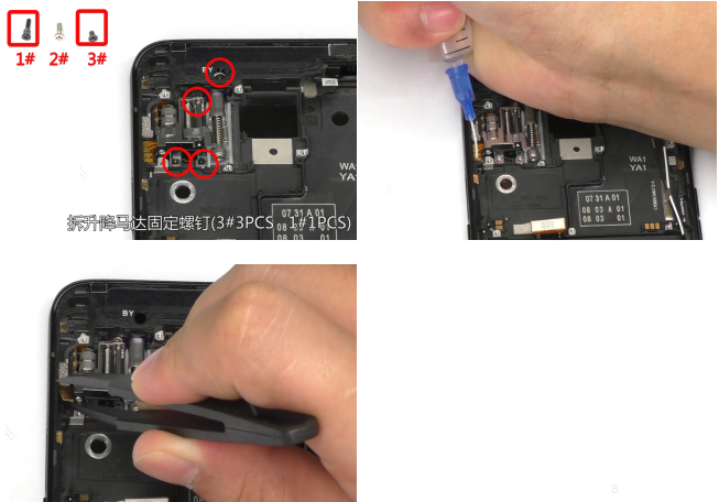 |
/ |
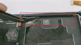
| 8 | Remove the RF cable | 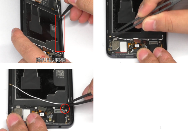 |
The BTB buckle must be pulled up vertically to prevent damage to the socket |
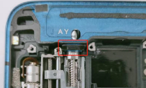
| 9 | Remove the antenna board/6-board | 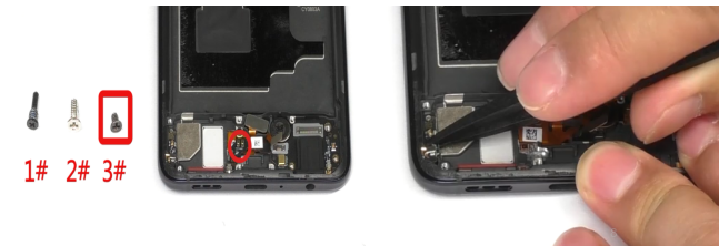 |
Please pay attention that the fingerprint sensor FPC is easy to be broken. |
| 10 | Remove the fingerprint sensor and vibration motor | 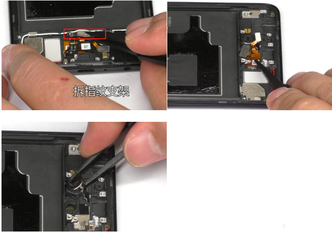 |
Please pay attention that the fingerprint sensor FPC is easy to be broken. |
| 11 | Clean up auxiliary materials like double-side adhesive tape | 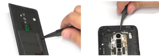 |
/ |
5. Assembly Step
5.1 Materials are required to be replaced after disassembly
| NO | Material name | Specification | Picture | Remark |
|---|---|---|---|---|
| 1 | battery pull tape | BLP735 transparent | 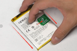 |
|
| 2 | Battery cover double-sided adhesive | AE001 | 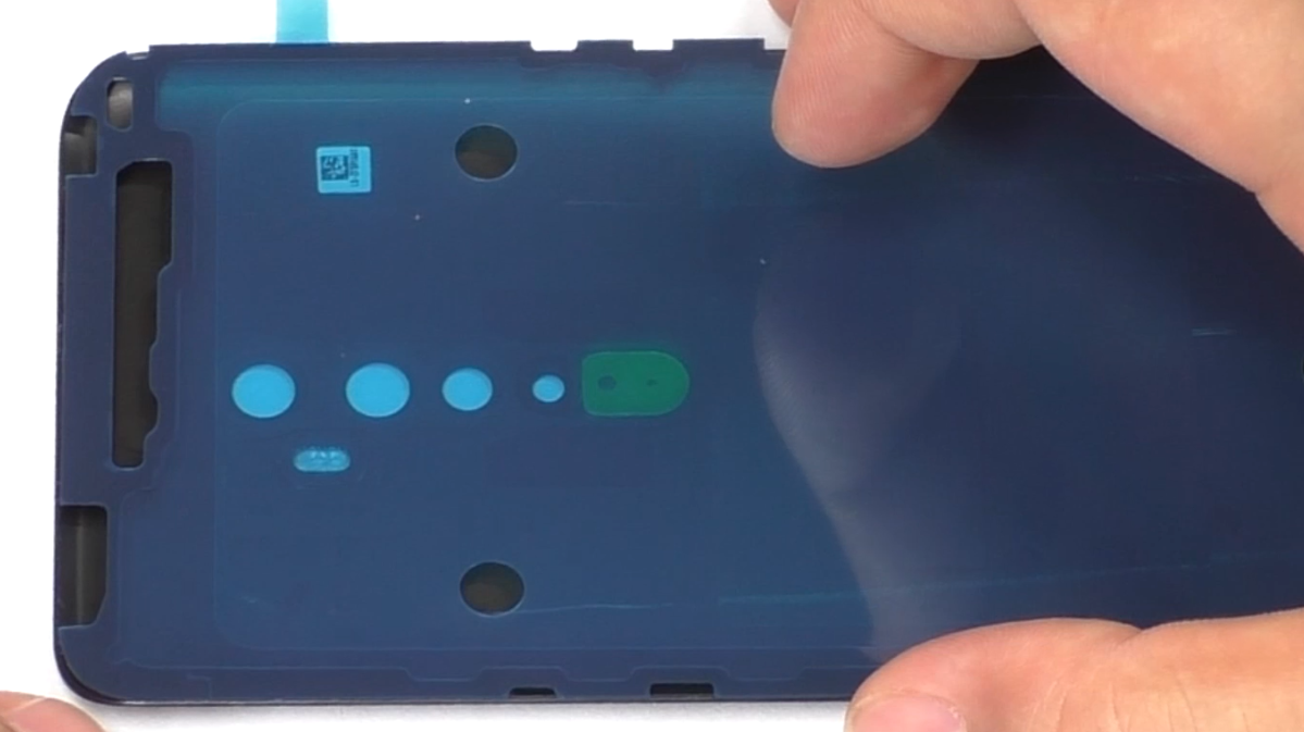 |
|
| 3 | Camera decorative ring double-sided adhesive | AE001 | 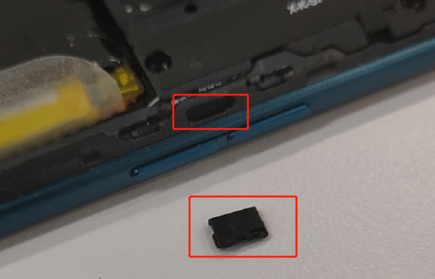 |
|
| 4 | Thermal gel | AE001 | 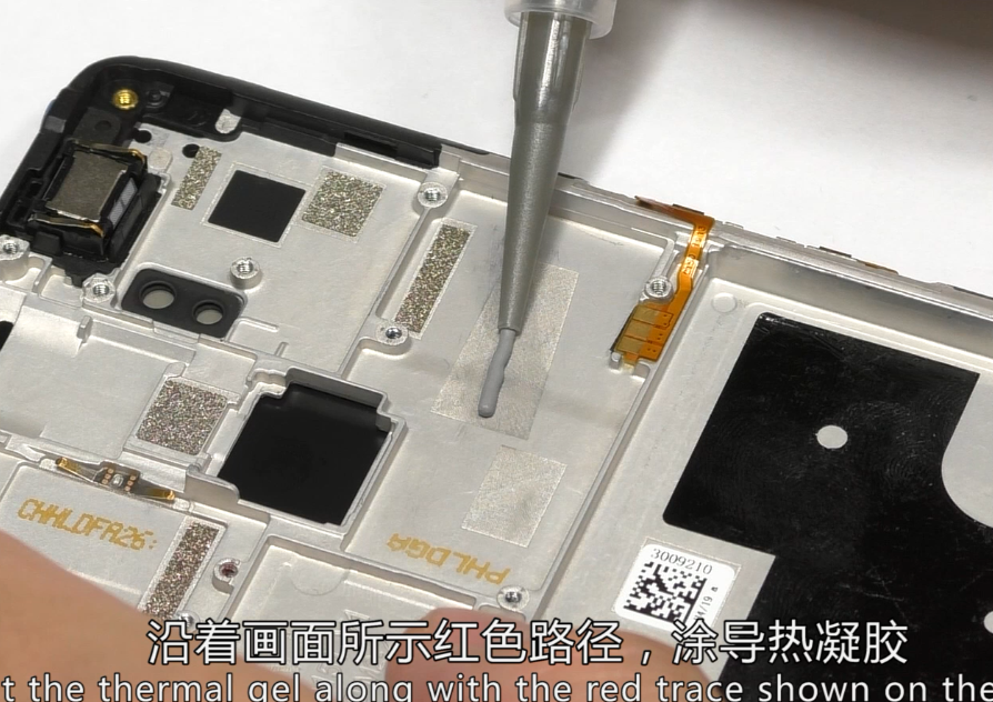 |
|
| 5 | Rear camera double-side tape | AE001 |  |
If you changed one of these cameras |
| NO | Details | Picture | Cautions |
|---|---|---|---|
| 1 | Assemble rear&front camera /lifting motor |
 |
Paste camera double-side tape before assemble and be careful not destroy the FPC |
| 2 | Assemble vibration motor and fingerprint sensor | 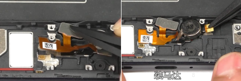 |
Fingerprint sensor double-sided adhesive tape must be replaced new one |
| 3 | Assemble antenna board and 6-board | 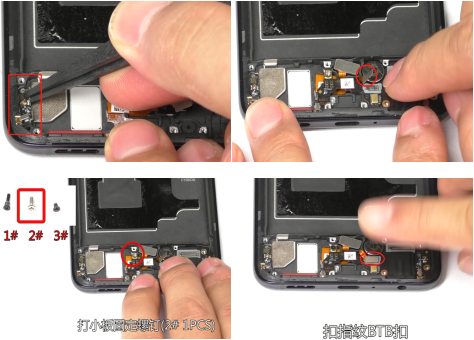 |
Pay attention to the fingerprint sensor FPC is easy to be broken |
| 4 | Assemble battery | 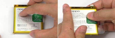 |
The tear paper must to be replaced a new one |
| 5 | Assemble the mainboard | 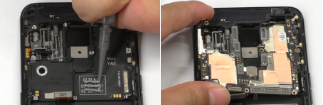 |
Don't forget to add thermal gel |
| 6 | Assemble RF cable | 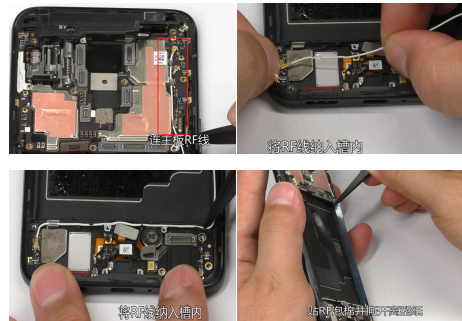 |
/ |
| 7 | Assemble rear camera | 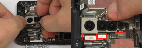 |
The BTB buckle must be pressed vertically to prevent damage to the socket |
| 8 | Assemble C-FPC, USB-FPC, speaker | 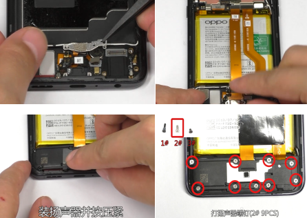 |
/ |
| 9 | Assemble the mainboard bracket | 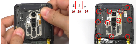 |
/ |
| 10 | Assemble battery cover/SIM card holder | 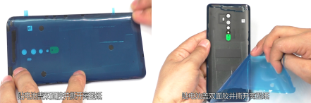 |
The “Battery cover double-sided adhesive” must to be replaced a new one |
6. Calibration
6.1 Leak Calibration
6.1.1 Calibration Scenario
The following fingerprint calibration must be performed after disassembling or replacing any of the main board, screen cover assembly or re-assemble after disassembling the whole machine
6.1.2 Calibration Tool
As shown in Figure 6.1.2
(Air bag for loading after sales materials)
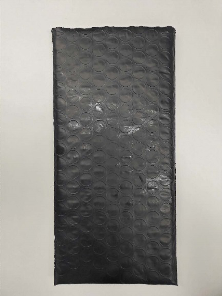
Figure 6.1.2
6.1.3 Calibration Method
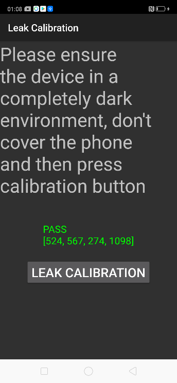
Calibration path: Enter *#899# in the dial interface>Aftersales Devices Calibration> Enter password “6776” >Infrared Proximity Calibration > Leak Calibration,Specific operations refer to calibration page hints:
Put the upper part of the phone into the air bag to expose the “Light Leakage Calibration” button. After the upper part is blocked by the air bag, click “Light Leak Calibration” and the phone will automatically calibrate, as shown in Figure 6.1.3. After the calibration is completed, it will automatically jump to the next fingerprint calibration item.
| Operation | 1. Make sure there is no material covering the phone, then press the infrared access calibration button. | 2. Put the upper part of the phone into the airbag and click ”Leak Calibration” | 3. After the calibration result is Pass, the calibration will automatically jump to the fingerprint calibration item after the calibration is completed. |
| Icon | 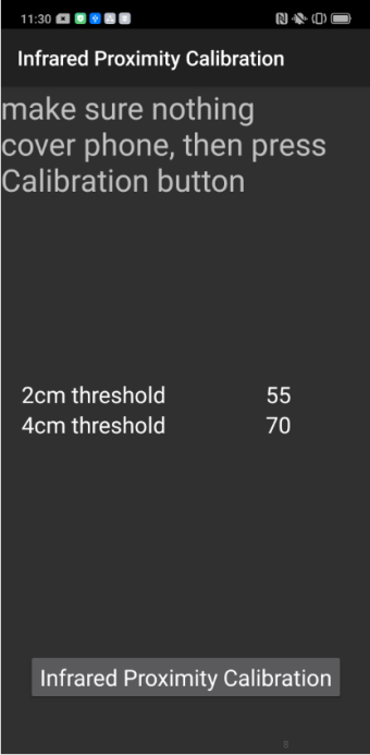 |
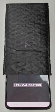 Figure 6.1.3 |
 |
6.2.1 Calibration Scenario
The following fingerprint calibration must be performed after disassembling or replacing any of the main board, fingerprint module, protective film, and screen cover assembly.
6.2.2 Calibration Tool
The calibration tool is shown in Figure 6.2.2-1:
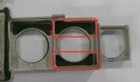
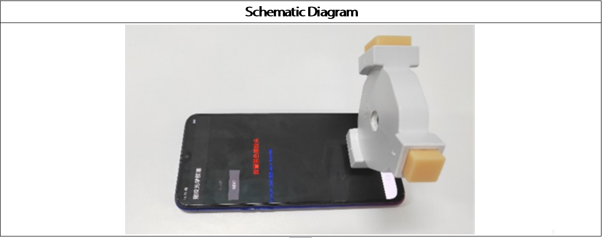
As shown in the Figure 6.2.2-2, the yellow stripe rubber head is with parallel stripes.
The schematic diagram during measure is shown in Figure 6.2.2-3:
6.2.3 Calibration Method
After the light Leak Calibration is completed, it will automatically jump to the fingerprint calibration item. Specific operations refer to calibration page hints:
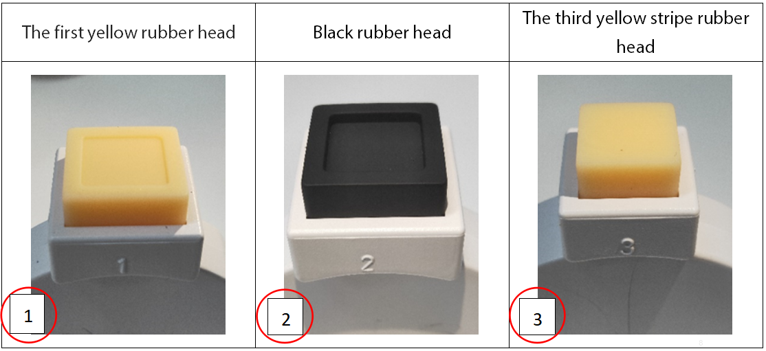
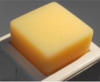
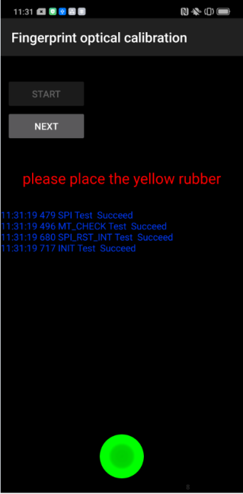
| Operation | 1. Click "START" to start calibration after it jumps into the fingerprint optical calibration, | 2. According to the prompt "please place the yellow rubber ", put the yellow rubber on the fingerprint spot area (the groove is facing down), and click "NEXT" until it prompts " please place the black rubber". |
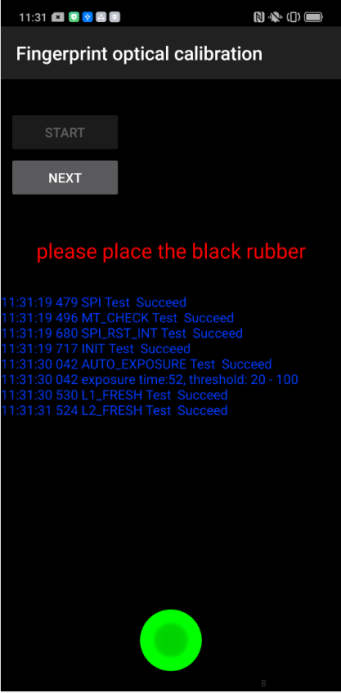
3.According to the prompt "please place the black rubber head", put the black rubber on the fingerprint spot area (the groove is facing down), click "NEXT" until the "please place the yellow stripe rubber " prompts to remove the black rubber ; |
|---|---|---|---|
| Icon | 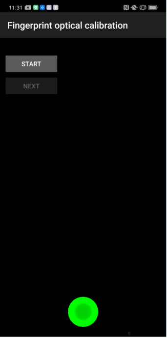 |
 |
 |
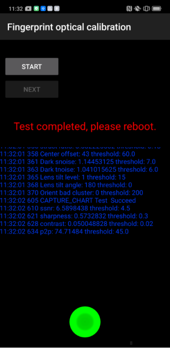
| Operation | 4. According to the prompt “Please place the yellow- striped rubber”, put the yellow stripe rubber (striped down) in the spot area, click “NEXT”; | 5. Prompt “Test completed, please reboot”, remove the yellow stripe rubber and complete the test; If the prompt is fail, check if there is a problem with the fingerprint module installation and recalibrate the test. |
Note: The stripe direction of the yellow stripe rubber should follow the long side of the phone. After the calibration is completed, the phone needs to be restarted |
| Icon | 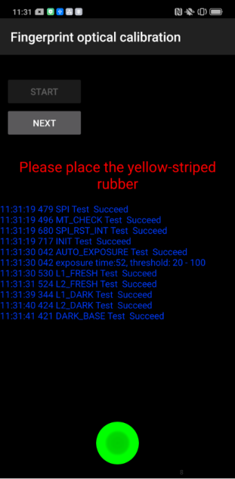 |
|
 |
6.3.1 Calibration Scenario
1. When the portrait mode is poorly blurred, the after-sales service center needs to calibrate the phone.
2. All devices must be calibrated after the phone has disassembled, or the portrait mode will be poorly blurred.
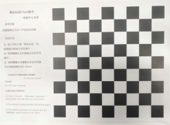
6.3.2 Calibration Tool
After-sales calibration Chart,
As shown in Figure 6.3.2-1:
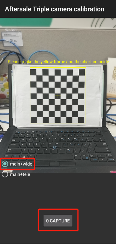
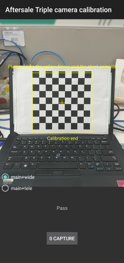
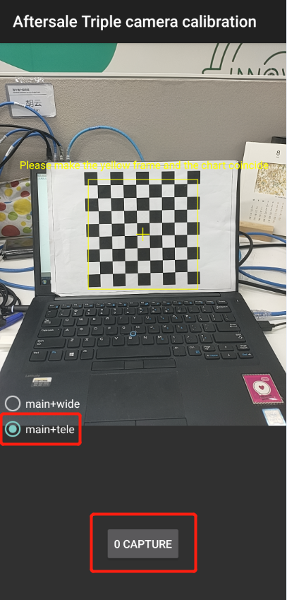
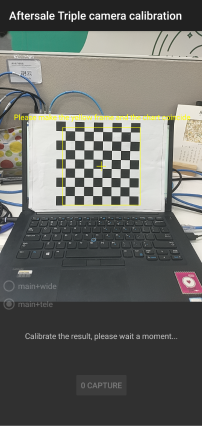
6.3.3 Calibration Method
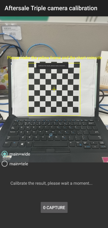
1. 1. Please align the yellow box with the edge of the chart, and then take a Photo. Then, do not operate the phone when the phone enters the computing interface until it displays “Pass” with the calibration completed.
| Calibration items |
Calibration interface | Calibration calculation process | Calibration result |
|---|---|---|---|
| Main + wide |
 |
 |
 |
| Main + tele |
 |
 |
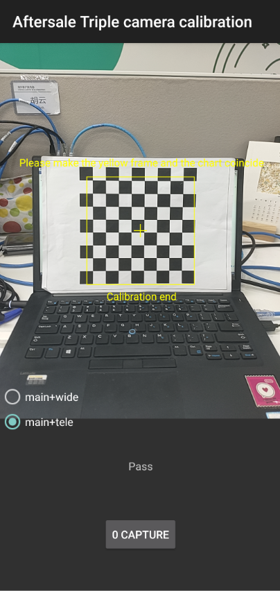 |
1. If it shows “Fail 69” during calibration, the lens is too far from the chart;
2. If it shows “Fail 70” during calibration, the lens is not parallel to the chart;
3. If it shows “Fail 68” during calibration, the lens is too close from the chart;
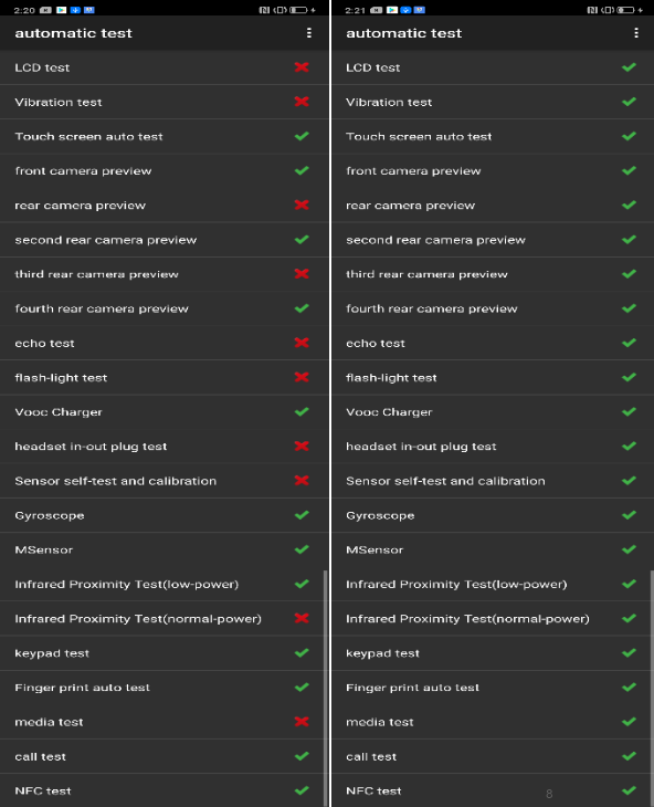
7. Function test
7.1 Test Path
Dialing Interface>Enter*#899#>Enter automatic test; The "Confirm" dialog box will pop up after the test complete, if there is no problem choose “Pass”, otherwise choose “Fail”.
7.2 Test Requirements
| No | Testing item | Testing requirements |
|---|---|---|
| 1 | LCD test | Observe the red, green, blue, white, black, gray, grayscale and color interface successively; If there are black spots, bright spots and other anomalies, the function is sound; |
| 2 | Vibration test | Get ear close to check the vibration from the motor for 3 seconds. If the motor vibrates normally(No noises or weak vibration), the function is sound; |
| 3 | Touch screen auto test | If the interface shows “PASS” and jumps to the next test, the function is sound; |
| 4 | Front camera preview | Align the front camera with a white surface and a black surface. If there is no black dot, black line or blurred screen on the screen after aligning the white surface, and there is no bright spot on the screen after aligning the black surface, the camera is sound; |
| 5 | Rear camera preview | Align the rear camera with a white surface, a black surface, and a surface with text. If there is no black dot, black line or blurred screen on the screen after aligning the white surface, there is no bright spot on the screen after aligning the black surface, white point or blurred screen, the camera is sound; |
| 6 | Second rear camera preview | Align the rear camera with a white surface, a black surface, and a surface with text. If there is no black dot, black line or blurred screen on the screen after aligning the white surface, there is no bright spot on the screen after aligning the black surface, white point or blurred screen, the camera is sound; |
| 7 | Third rear camera preview | Align the rear camera with a white surface, a black surface, and a surface with text. If there is no black dot, black line or blurred screen on the screen after aligning the white surface, there is no bright spot on the screen after aligning the black surface, white point or blurred screen, the camera is sound; |
| 8 | Fourth rear camera preview | Align the rear camera with a white surface, a black surface, and a surface with text. If there is no black dot, black line or blurred screen on the screen after aligning the white surface, there is no bright spot on the screen after aligning the black surface, white point or blurred screen, the camera is sound; |
| 9 | Echo test | Testing Main MIC: Blow the air to the MIC hole on the bottom of the phone. If the receiver (earphone) sounds, the function of Main MIC is sound; Testing Sub MIC: Blow the air to the sub MIC hole on the top of the phone. If the speaker sounds, the function of Main MIC is sound; |
| 10 | Flash-light test | Open the flashlight. If it can be opened normally with color deviations, the function is sound; |
| 11 | VOOC Charger | Use the original OPPO adapter and USB cable to charge. If the interface shows “PASS” and jumps to the next test, the function is sound; |
| 12 | Headset in-out plug test | Plug in and out the earphone with the OPPO earphone. If the interface shows “PASS” and jumps to the next test, the function is sound; |
| 13 | Sensor self-test and calibration | When the phone enters into the Sensor self-calibration interface, the phone must be placed on the desk flatly. Then click the first calibration item. After the test is passed, it will automatically jump to the next test item |
| 14 | Gyroscope | Take the mobile phone to draw the "8" word graphic. If the interface shows “PASS” and jumps to the next test, the function is sound; |
| 15 | M-Sensor | Shake the phone from the left to the right side. If the interface shows “PASS” and jumps to the next test, the function is sound; |
| 16 | Infrared Proximity test(low power) | Use the palm to cover the light sensor hole, and the screen will turn green from black. If the interface shows “PASS” and jumps to the next test, the function is sound; |
| 17 | Infrared Proximity test(normal- power) | Use the palm to cover the light sensor hole, and the screen will turn green from black. If the interface shows “PASS” and jumps to the next test, the function is sound; |
| 18 | Keypad test | Press the power key and volume key one by one. If keys can be pressed normally and the interface jumps to the next test, the function is sound; |
| 19 | Finger print auto test | If the interface shows “PASS” and jumps to the next test, the function is sound; |
| 20 | Media test | Click the “20-4K(-3db)signal” to test the sound of the media function for 5s. If there is no silence, weak sound, noises, and breaking sound, the interface shows “PASS” and jumps to the next test, the function is sound; |
| 21 | Call test | If the phone has been installed with the operator's SIM card, dial the corresponding operator's phone number. If no card is installed, call the 112 to test (Calling the Operator is recommended). If the call can be performed normally and the receiver is without noises or weak sounds, the function is sound; |
| 22 | NFC test | Close the phone of the rear camera area to the NFC card reader. If the signal light of the card reader changes from red to green with “Beep” sound, the interface shows “PASS” and jumps to the next test, the function is sound; |
8. Cautions
1. Calibration is required after maintenance;
2. After assembly, calibration must be performed before functional testing to ensure proper function after maintenance;
3. Sensory test items require staff to judge the results. For example, LCD test, vibration test, pre-test, post-test, flash test, echo test, audio test, and call test are all human judgment results. Therefore, the judgment result must be followed. Test requirements judgment;
4. It is forbidden to use the return key to judge the result in advance if the test item is not tested.
------ Overseas Customer Service Technical Support Group