F15/A91 Service Manual -V1

Confidential
Content
1. Guidance
1.1 Warnings
1.2 Cautions
2. General Repair Information
3. Phone Structure Diagram
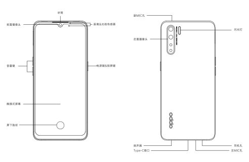
3.1 Product Appearance
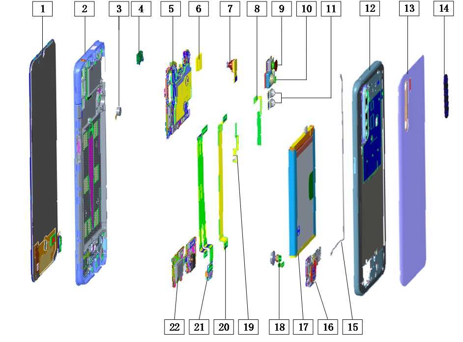
3.2 Phone Structure Explosive View
3.3 Explosive Map BOM
4. Disassembly Steps
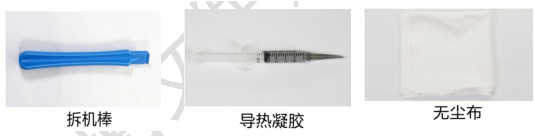
4.1 Disassembly Tools
4.2 Preparation
4.3 Disassembly Steps
5. Assembly Steps
5.1 Bill of Must-Be-Replaced Materials
5.2 Assembly Steps
6. After-sale calibration
6.1 Leak Calibration
6.1.1 Calibration Scenario
6.1.2 Calibration Tool
6.1.3 Calibration Method
6.2 Fingerprint optical calibration
6.2.1 Calibration Scenario
6.2.2 Calibration Tool
6.2.3 Calibration Method
6.3 Dual Camera Calibration
6.3.1 Calibration Scenario
6.3.2 Calibration Tool
6.3.3 Calibration Method
7. Function Test
7.1 Test Path
7.2 Test Requirements
8. General Cautions
1.Guidance
The purpose of this document is only to guide OPPO technicians to carry out maintenance service to OPPO products. The content shall be keep in confidential, only avail be able to OPPO authorized service centers, and cannot be provided to third parties without authorization. Please follow the regulations and the guidance for maintenance service. For any problems, please contact China HQ in time.
1.1 Warnings
1. Care must be taken on installation in vehicles fitted with electronic engine management systems and ABS (Anti–skid Braking Systems). Under certain fault conditions, emitted RF energy can affect their operation. If necessary, consult the vehicle dealer/manufacturer to determine the immunity of vehicle electronic systems to RF energy.
2. Phones must not be operated in areas likely to contain potentially explosive atmospheres, e.g. petrol stations (service stations), blasting areas etc.
3. Operation of any radio transmitting equipment, including cellular telephones, may interfere with the functionality of inadequately protected medical devices. Consult a physician or the manufacturer of the medical device if you have any questions. Other electronic equipment may also be subject to interference
1.2 Cautions
1. Repair services and calibrations must be undertaken by qualified personnel only.
2. Use only approved components as specified in the parts list.
3. Ensure all components, modules screws and insulators are correctly re-fitted after servicing and alignment.
4. Electrostatic discharge is the main cause of damage to sensitive components of electronic products. Service centers must operate in accordance with OPPO's requirements for ESD protection. Ensure all work is carried out at an ESD workstation and that an ESD wristband is worn.
2.General Repair Information
1.Ensure all work is carried out at an ESD workstation and that an ESD wristband is worn before starting maintenance.2.Wear ESD gloves to avoid oil stains and fingerprints.
3.Use protective films to protect the display, camera, camera lens to prevent dust and scratches.
4.Use a clean cloth, ESD brush and alcohol (Concentration above 95%) for appearance cleaning. Do not use other items (such as an eraser) for cleaning to prevent the protective layer from being scratched, which may lead to oxidation and corrosion.
5.Faulty welded mechanical parts (except shield cover and shield frame parts) can only be replaced and not repairable.
6.Use accessories provided by OPPO.
7.Check the contacts or solder joints of devices that may cause simple faults (e.g. soldered interfaces or switches). Re-weld if necessary (only for service centers where lead-free soldering is available) and clean the flux remaining after soldering.
8.Use the equipment provided by OPPO to test the phone (e.g. When the charging function of the device is abnormal, do use the original OPPO adapter to test to ensure the accuracy of the test results).
9.Fill in the fault phenomenon code and fault reason code according to the actual situation, and accurately enter the replacement material code in the CRM system.
10.For more information about products,
Mainland China please visit:
http://172.16.41.122:8888/kbaseui-dev/main.do
Regions except for Mainland China please visit:
ftp://ftpex.oppo.com:919/ or
https://oppo knowledge.custhelp.com/app/home/loc/zh_CN
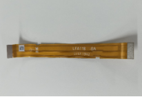
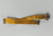
3. Phone Structure Diagram
3.1 Product Appearance
3.2 Phone Structure Explosive View
3.3 Explosive Map BOM
|
No. |
Material Name(After-sales) |
Physical Figure |
Specifications |
QTY |
Unit |
|---|---|---|---|---|---|
|
1 |
Screen |
|
((1) OLED Display Screen |
1 |
PCS |
|
(2) Middle Frame |
1 |
PCS |
|||
|
(3) Motor |
1 |
PCS |
|||
|
(8)Volume Key FPC |
1 |
PCS |
|||
|
(19)Power Key FPC |
1 |
PCS |
|||
|
LCM FPC BTB waterproof foam |
1 |
PCS |
|||
|
LCM FPC Through Hole Waterproof Silicone Case |
1 |
PCS |
|||
|
Capacitive touch screen protective film |
1 |
PCS |
|||
|
2 |
Receiver |
|
((4)Receiver |
1 |
PCS |
|
3 |
SIM card lock sticker |
|
(6)SIM card lock sticker |
1 |
PCS |
|
4 |
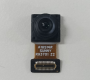
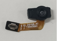
Front camera |
|
(7)Front camera |
1 |
PCS |
|
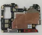
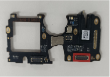
5 |
Mainboard |
|
(5)PCB semi-finished |
1 |
PCS |
|
waterproof paste |
1 |
PCS |
|||
|
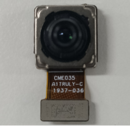
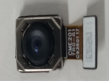
6 |
Rear Camera |
|
(10)Camera |
1 |
PCS |
|
Camera conductive fabric(main) |
1 |
PCS |
|||
|
Camera BTB conductive fabric(main) |
1 |
PCS |
|||
|
Camera preposition sponge(main) |
1 |
PCS |
|||
|
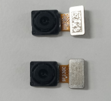
7 |
Wide-angle Camera |
|
(9)Camera |
1 |
PCS |
|
Camera conductive fabric(sub) |
1 |
PCS |
|||
|
Camera BTB conductive fabric(main) |
1 |
PCS |
|||
|
Camera preposition sponge(sub) |
1 |
PCS |
|||
|
8 |
Camera |
|
(11)Rear camera 2M |
2 |
PCS |
|
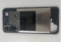
9 |
Mainboard Cover |
|
(12)Motherboard bottom cover |
1 |
PCS |
|
(14)Camera lens |
1 |
PCS |
|||
|
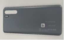
10 |
Battery cover |
|
(13)Battery cover |
1 |
PCS |
|
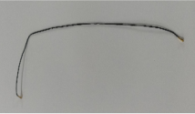
11 |
RF connecting cable |
|
(15)RF connecting cable |
1 |
PCS |
|
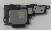
12 |
Speaker BOX |
|
(16)Speaker BOX |
1 |
PCS |
|
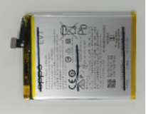
13 |
Battery |
|
(17)Battery |
1 |
PCS |
|
14 |
Touch Panel Assembly |
|
(18)Touch Panel Assembly |
1 |
PCS |
|
15 |
L board FPC |
|
(20))LCD FPC |
1 |
PCS |
|
Screen BTB conductive cloth |
1 |
PCS |
|||
|
16 |
USB board FPC |
|
(21)USB FPC |
1 |
PCS |
|
Main FPC conductive fabric |
1 |
PCS |
|||
|
USB sealing silicon rubber sleeve |
1 |
PCS |
|||
|
17 |
Antenna board |
|
(22))PCB semi-finished |
1 |
PCS |
|
Headphone holder silicone case |
1 |
PCS |
Note:This table is used only for the name of the annotation but not for the preparation of materials. Please refer to the Price List of OPPO Mobile Phone Original Accessories (for Mainland China)/Price List of Commonly-Used Materials and Accessories (Regions except for Mainland China) for the preparation.
4. Disassembly Steps
4.1 Disassembly Tools
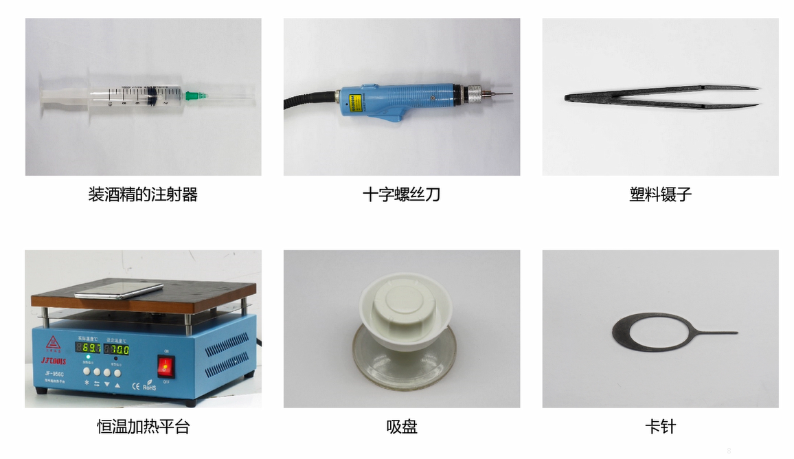
4.2 Preparation
1. The phone must be powered off before disassembly.
2. Way to Power Off:
System Power Off: Press the power key then slide to power off.
Forced Power Off: Long press the volume “+” key and power key for about 8 seconds until the display is off.
4.3 Disassembly Steps
|
Step |
Content |
Figure |
Cautions |
|---|---|---|---|
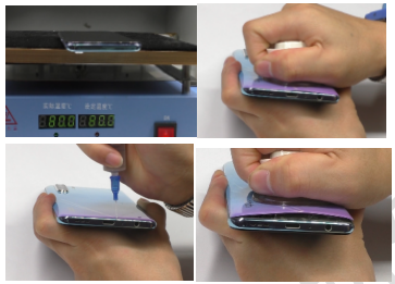
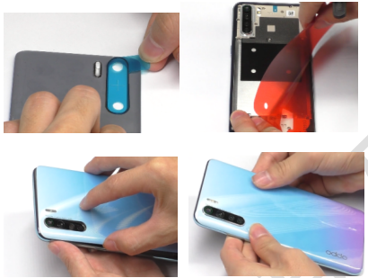
|
1 |
Disassemble the battery cover |
|
(1) Avoid heating the camera. Heating requirements: 70 ° C -80 ° C for 5-10 mins; |
|
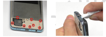
2 |
Disassemble Mainboard Cover |
|
(1)The disassembly rod needs to be wrapped with a dust-free cloth to avoid scratching the mainboard cover. |
|
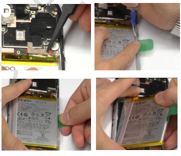
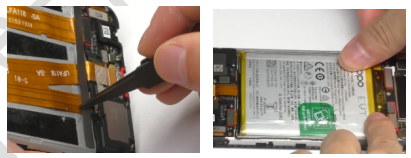
3 |
Disassemble the battery |
|
1.Add 0.2ml of alcohol to the top and bottom of the handle, and stand the phone sideways for 15 seconds until the alcohol spreads; Note: During disassembly of the battery, it is necessary to avoid bending and deformation of the middle part of the battery as much as possible. |
|
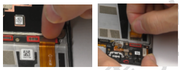
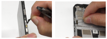
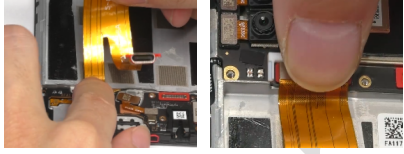
4 |
Disassemble USB board FPC |
|
(1)Use nails to disassemble the BTB buckle. Do not use too much force. |
|
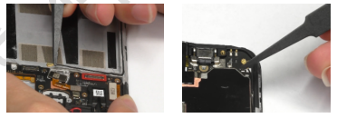
5 |
Disassemble L board FPC |
|
(1)Use nails to disassemble the BTB buckle. Do not use too much force. |
|
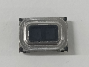
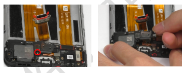
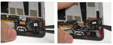
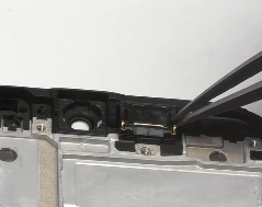
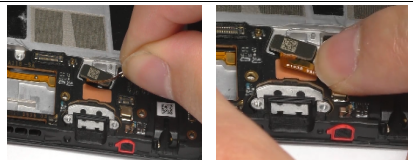
6 |
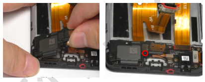
Disassemble speaker BOX |
|
(1) Disassemble the screws before disassembling the speaker. |
|
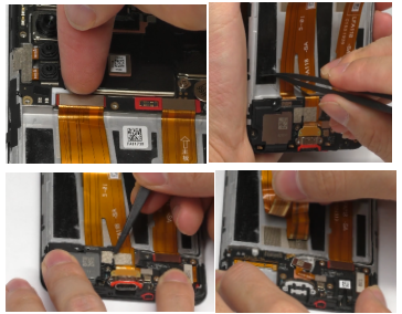
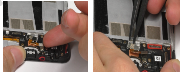
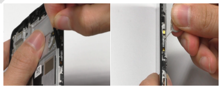
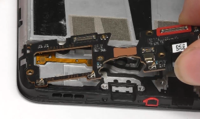
7 |
Disassemble RF connecting cable |
|
(1) Pay attention to the disassembly angle and strength |
|
8 |
Disassemble touch panel assembly |
|
(1)Disassemble the BTB buckle first and then the touch panel assembly |
|
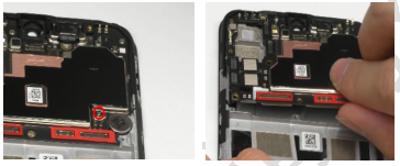
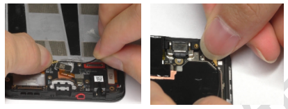
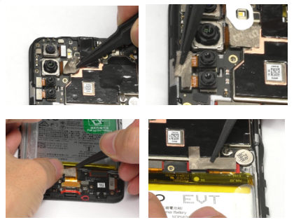
9 |
Disassemble Antenna board |
|
(1) Gently lift up the Antenna board with plastic tweezers |
|
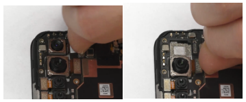
10 |
Disassemble Rear Camera |
|
(1) Pay attention to the disassembly angle and strength |
|
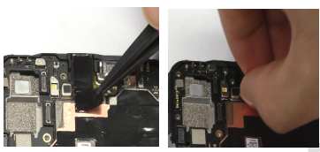
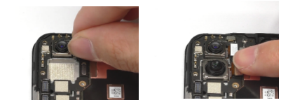
11 |
Disassemble Front camera |
|
(1)Disassemble the graphite sheet first, then disassemble the camera |
|
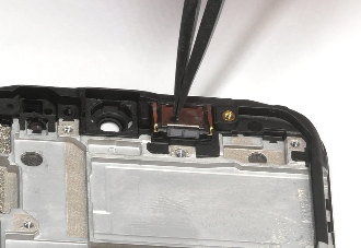
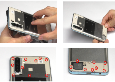
12 |
Disassemble |
|
(1)First remove the screws 1pcs as shown |
|
13 |
Disassemble |
|
(1)The receiver needs to be reused |
|
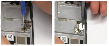
14 |
Disassemble |
|
(1)Put a small amount of alcohol on the FPC first, and then disassemble the motor with tweezers |
|
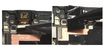
15 |
Disassemble |
|
(1) Lift the FPC with pin |
|
16 |
Disassemble |
|
(1) Lift the FPC with pin |

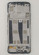
手机拆解全家图
5. Assembly Steps
5.1 Bill of Must-Be-Replaced Materials
|
No. |
Code |
Material |
SPEC. |
QTY |
Remark |
|---|---|---|---|---|---|
|
1 |
4879314 |
Battery cover adhesive |
FA117 black |
1 |
Must be replaced after disassembling the battery cover adhesive |
|
2 |
4879310 |
Camera decorative ring double-sided adhesive |
FA117 black |
1 |
Must be replaced after disassembling the battery cover adhesive |
|
3 |
4875006 |
battery pull tape |
BLP681 transparent |
1 |
Must be replaced after disassembling the battery |
|
4 |
4879321 |
Front camera graphite sheet |
FA117 single-sided adhesive |
1 |
Must be replaced after disassembling Front camera/Mainboard/Screen |
|
5 |
4879332 |
Camera BTB conductive fabric(main) |
FA117 single-sided adhesive |
1 |
Must be replaced after disassembling Rear Camera/Wide-angle Camera |
|
6 |
4879334 |
Main FPC conductive fabric |
FA117 single-sided adhesive |
1 |
Must be replaced after disassembling USB board FPC |
|
7 |
4879333 |
Screen BTB conductive cloth |
FA117 single-sided adhesive |
1 |
Must be replaced after disassembling L board FPC |
5.2 Assembly Steps
|
Step |
Content |
Figure |
Cautions |
|
1 |
Install the Power Key FPC |
|
(1) Level the Power Key FPC first, then press gently |
|
2 |
Install the Volume Key FPC |
|
(1) Level the Volume Key FPC first, then press gently |
|
3 |
Install the Vibration motor |
|
(1) Level the Vibration motor first, then press gently |
|
4 |
Install the Receiver |
|
(1) Level the Receiver first, then press gently |
|
5 |
Install the Mainboard |
|
(1)Insert the motherboard from the left side, confirm the leveling, and then hit the fixing screw 1pcs |
|
6 |
Install the Rear Camera |
|
(1)Level the Camera first then attach the BTB button |
|
7 |
Install the Front camera |
|
(1)Install the camera first, then attach the graphite sheet |
|
8 |
Install the Antenna board |
|
(1)Insert the Antenna board from the left side, confirm the leveling, and then press gently |
|
9 |
Install the Touch Panel Assembly |
|
(1)Level the Touch Panel Assembly first then attach the BTB button |
|
10 |
Install the RF connecting cable |
|
(1)Put the RF connecting cable into the trunk |
|
11 |
Install the USB board FPC |
|
(1)Attach the BTB button then flatten the FPC |
|
12 |
Install the speaker BOX |
|
(1)Insert the speaker BOX from the left side, confirm the leveling, and then hit the fixing screw 1pcs |
|
13 |
Install the Battery |
|
(1)First stick the Bottom sponge of battery bin |
|
14 |
Install the conductive fabric |
|
(1)Pay attention to flat |
|
15 |
Install the Mainboard Cover |
|
(1)Install the Mainboard Cover from the top of the camera |
|
16 |
Install the Battery cover |
|
(1)Gently press the battery cover to ensure it is in place |
|
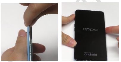
17 |
Turn on the phone to check its functions |
|
(1)Begin after-sale calibration test |
6. After-sale calibration
It must be calibrated after disassembling or replacing the phone, Calibration include Light leakage calibration,Fingerprint optical calibration and Dual Camera Calibration. After the calibration is completed, the phone needs to be restarted.
6.1 Leak Calibration
6.1.1 Calibration Scenario
The following fingerprint calibration must be performed after disassembling or replacing any of the main board, screen cover assembly or re-assemble after disassembling the whole machine6.1.2 Calibration Tool
Air bag for loading after sales materials
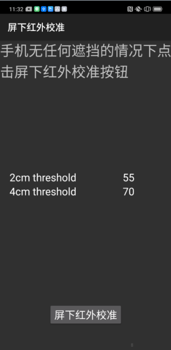
6.1.3 Calibration Method
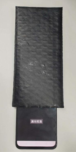
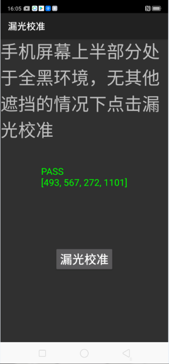
Calibration path: Enter *#899# in the dial interface>Aftersales Devices Calibration> Enter password “6776” >Infrared Proximity Calibration > Leak Calibration,Specific operations refer to calibration page hints:
Put the upper part of the phone into the air bag to expose the “Light Leakage Calibration” button. After the upper part is blocked by the air bag, click “Light Leak Calibration” and the phone will automatically calibrate, as shown in Figure 6.1.3. After the calibration is completed, it will automatically jump to the next fingerprint calibration item.
|
Operation |
1. Make sure there is no material covering the phone, then press the infrared access calibration button. |
2. Put the upper part of the phone into the airbag and click ”Leak Calibration” |
3. After the calibration result is Pass, the calibration will automatically jump to the fingerprint calibration item after the calibration is completed. |
|---|---|---|---|
|
Icon |
|
|
|
6.2 Fingerprint optical calibration
6.2.1 Calibration Scenario
The following fingerprint calibration must be performed after disassembling or replacing any of the main board, fingerprint module, protective film, and screen cover assembly.
6.2.2 Calibration Tool
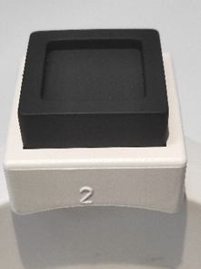
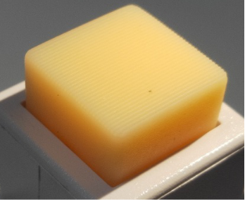
|
The first yellow rubber head |
Black rubber head |
The third yellow stripe rubber head |
|---|---|---|
|
|
|
|
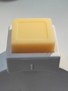
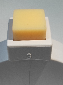
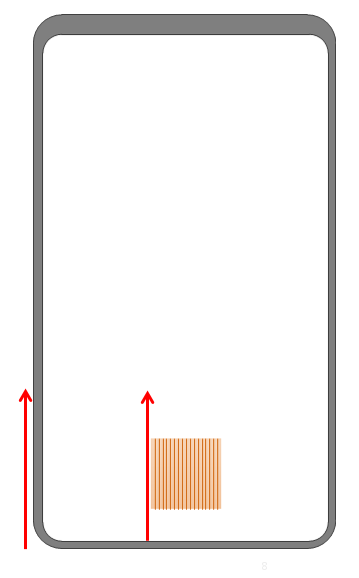
As shown in the Figure 6.2.2-2, the yellow stripe rubber head is with parallel stripes.
(Figure 6.2.2-2)
The schematic diagram during measure:
|
Schematic Diagra |
|---|
|
|
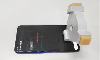
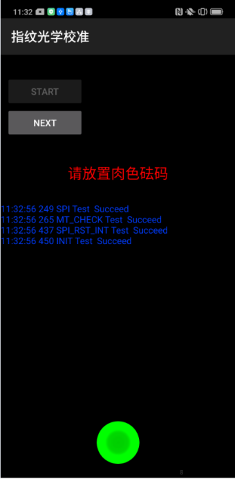
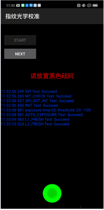
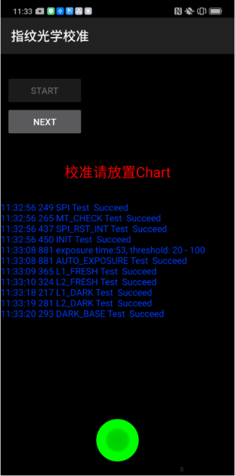
6.2.3 Calibration Method
After the light Leak Calibration is completed, it will automatically jump to the fingerprint calibration item. Specific operations refer to calibration page hints:
|
Operation |
1. Click "START" to start calibration after it jumps into the fingerprint optical calibration, |
2. According to the prompt "please place the yellow rubber ", put the yellow rubber on the fingerprint spot area (the groove is facing down), and click "NEXT" until it prompts " please place the black rubber". |
3.According to the prompt "please place the black rubber head", put the black rubber on the fingerprint spot area (the groove is facing down), click "NEXT" until the "please place the yellow stripe rubber " prompts to remove the black rubber ; |
|---|---|---|---|
|
Icon |
|
|
|
|
Operation |
4. According to the prompt “Please place the yellow- striped rubber”, put the yellow stripe rubber (striped down) in the spot area, click “NEXT”; |
5. Prompt “Test completed, please reboot”, remove the yellow stripe rubber and complete the test; |
Note: The stripe direction of the yellow stripe rubber should follow the long side of the phone. After the calibration is completed, the phone needs to be restarted |
|
Icon |
|
|
|


6.3 Dual Camera Calibration
6.3.1 Calibration Scenario
1. When the portrait mode is poorly blurred, the after-sales service center needs to calibrate the phone.
2. All devices must be calibrated after the phone has disassembled, or the portrait mode will be poorly blurred.
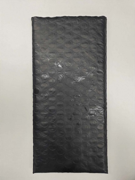
6.3.2 Calibration Tool
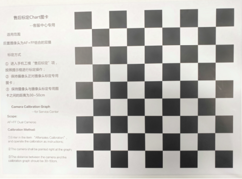
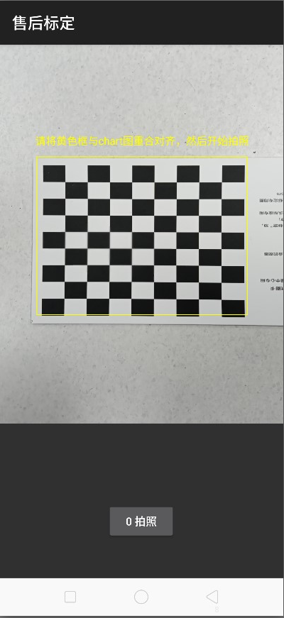
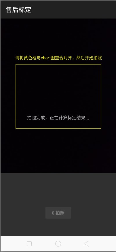
After-sales calibration Chart:
6.3.3 Calibration Method
1. 1. Please align the yellow box with the edge of the chart, and then take a Photo. Then, do not operate the phone when the phone enters the computing interface until it displays “Pass” with the calibration completed.
|
Calibration interface |
Calibration Calculation Process Interface |
Calibration PASS result interface |
|---|---|---|
|
|
|
|
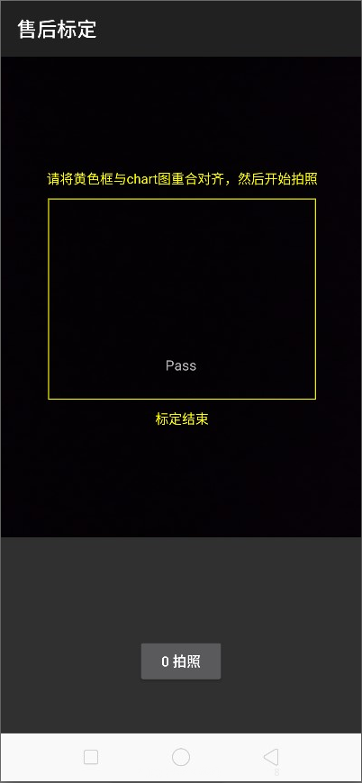
Precautions:
1. If it shows “Fail 69” during calibration, the lens is too far from the chart;
2. If it shows “Fail 70” during calibration, the lens is not parallel to the chart;
3. If it shows “Fail 68” during calibration, the lens is too close from the chart;
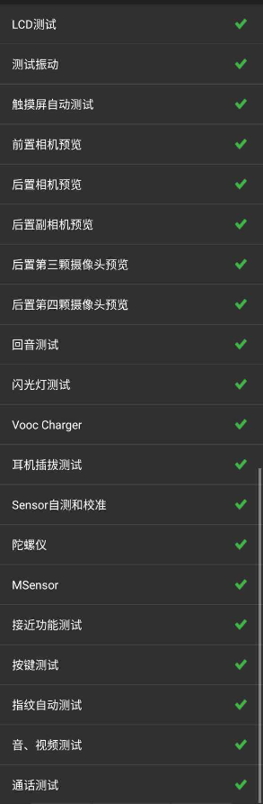
7. Function Test
7.1 Test Path
Dialing Interface>Enter*#899#>Enter automatic test; The "Confirm" dialog box will pop up after the test complete, if there is no problem choose “Pass”, otherwise choose “Fail”.
7.2 Test Requirements
|
No. |
Test Items |
Test Requirements |
|---|---|---|
|
1 |
LCD Test |
Observe the red, green, blue, white, black, gray, grayscale and color interface successively; If there are black spots, bright spots and other anomalies, the function is good; |
|
2 |
Vibration Test |
Get ear close to check the vibration from the motor for 3 seconds.If the motor vibrates normally(No noises or weak vibration), the function is good; |
|
3 |
Touch Screen Auto Test |
If the interface shows “PASS” and jumps to the next test, the function is good; |
|
4 |
Front Camera Preview |
Align the rear camera with a white surface and a black surface. If there is no black dot, black line or blurred screen on the screen after aligning the white surface, and there is no bright spot on the screen after aligning the black surface, the camera is good; |
|
5 |
Rear camera preview |
Align the rear camera with a white surface, a black surface, and a surface with text. If there is no black dot, black line or blurred screen on the screen after aligning the white surface, there is no bright spot on the screen after aligning the black surface, white point or blurred screen, the camera is good; |
|
6 |
Second rear camera preview |
Align the rear camera with a white surface, a black surface, and a surface with text. If there is no black dot, black line or blurred screen on the screen after aligning the white surface, there is no bright spot on the screen after aligning the black surface, white point or blurred screen, the camera is good; |
|
7 |
Rear third camera preview |
Check if it can open normally, enter camera preview for 5 seconds. |
|
8 |
Rear fourth camera preview |
Check if it can open normally, enter camera preview for 5 seconds. |
|
9 |
Echo test |
Testing Main MIC: Blow the air to the MIC hole on the bottom of the phone. If the receiver (earphone) sounds, the function of Main MIC is good; |
|
10 |
Flashlight Test |
Open the flashlight. If it can be opened normally with color deviations, the function is good; |
|
11 |
Charging Test(VOOC) |
Use the original OPPO adapter and USB cable to charge. If the interface shows “PASS” and jumps to the next test, the function is good; |
|
12 |
Headset in-out Plug test |
Plug in and out the earphone with the OPPO earphone. If the interface shows “PASS” and jumps to the next test, the function is good; |
|
13 |
Sensor Self-test and Calibration |
When the phone enters into the Sensor self-calibration interface, the phone must be placed on the desk flatly. Then click the first calibration item. After the test is passed, it will automatically jump to the next test item; |
|
14 |
Gyroscope Test |
Take the mobile phone to draw the "8" word graphic. If the interface shows “PASS” and jumps to the next test, the function is good; |
|
15 |
M-Sensor Test |
Shake the phone from the left to the right side. If the interface shows “PASS” and jumps to the next test, the function is good; |
|
16 |
Proximity-sensor Test(100mA) |
Use the palm to cover the light sensor hole, and the screen will turn green from black. If the interface shows “PASS” and jumps to the next test, the function is good; |
|
17 |
Keypad Test |
Press the power key and volume key one by one. If keys can be pressed normally and the interface jumps to the next test, the function is good; |
|
18 |
Fingerprint Auto Test |
If the interface shows “PASS” and jumps to the next test, the function is good; |
|
19 |
Media test |
Click the “20-4K(-3db)signal” to test the sound of the media function for 5s. If there is no silence, weak sound, noises, and breaking sound, the interface shows “PASS” and jumps to the next test, the function is good; |
|
20 |
Call test |
If the phone has been installed with the operator's SIM card, dial the corresponding operator's phone number. If no card is installed, call the 112 to test (Calling the Operator is recommended). If the call can be performed normally and the receiver is without noises or weak sounds, the function is good; |
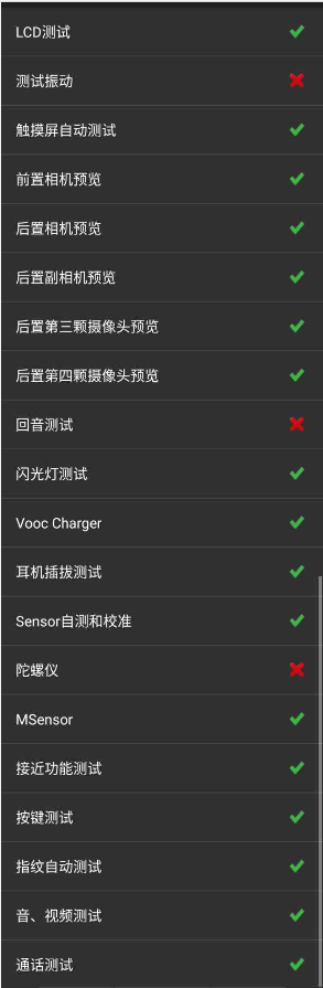
After the above 20 items are tested, they will prompt to the test result interface. If the test PASS, project will show “√”; If the test FAIL, project will show “×” as shown below.
8. General Cautions
8.1When disassembling (front/rear) camera and fingerprint module, pay attention to protect the camera lens with low mucosa;
8.2 If it involves replacing the screen assembly, the main board or cleaning the original thermal gel, it is necessary to apply the thermal conductive gel according to the above installation steps;
8.3For OPPO A91/F15 Disassembly Video Please visit:
Baidu network disk:https://pan.baidu.com/s/18GdCD0frdn11PpeOKu_wlQ
Extraction code:sixz
FTP: Overseas Customer Service--- OPPO Technical Service--- Product Material--- F15&A91
|
Version |
Date |
Draft |
Review |
Approve |
Modified content |
|---|---|---|---|---|---|
|
V1.0 |
2020-01-14 |
Yang Feng yuan, |
Li |
Huang |
1.First Edition |