F11 Pro Service Manual V1.2
Content
1.Guidance
2.General Repair Information
3.Product Overview
4.Exploded View of Phone's Structure
5.Disassembly Steps
6.Installation steps
7.Calibration
8.Post-maintenance functional test
9.Precautions
1. Guidance
1.1 Guidance Overview:
The purpose of this document is to help OPPO level1 and level 2 maintenance engineers to carry out service to OPPO products. This Service Manual is to be used only by authorized OPPO maintenance service centers, and the content shall be keep in confidential. Please note that OPPO provides also other guidance documents (e.g. Technical Service Bulletins) for maintenance service cooperative corporations, therefore, please follow these regularly and comply with the given instructions. While every endeavor has been made to ensure the accuracy of this document, some errors may exist. If you find any error or if you can offer further suggestions, please notify OPPO by using the address below: zhouyangguang@oppo.com. Please keep in mind also that this document is continuously being updated and modified, please keep watching out for the newest version.
1.2. Warnings and Cautions:
Please refer to the phone's user guide for instructions relating to operation, service and maintenance including important safety information. Note the following:
1. Service centers may be required to install the handset's vehicle-mounted system in vehicles. Under certain fault conditions, the handset's RF signals may affect the operation of the vehicles' electric power management systems and anti–skid braking systems (ABSs). If necessary, consult the dealer/manufacturer to determine the immunity of vehicle electronic systems to RF energy.
2. The handset must not be operated in areas likely to contain potentially explosive atmospheres, such as petrol stations, gas stations and blasting areas.
3. Operation of any radio transmitting equipment, including handsets, may interfere with the functionality of the medical devices protected by industrial mechanisms. Consult the manufacturer of the medical devices if necessary. Other electronic equipment may also be subject to interference.
2. General Repair Information
In this section the technician will get some general hints to carry out repairs:
Customer service personnel can download and read product documentation on:Download and read the product guide or user manual on the site: ftp://:ftp://wxfuwu@172. 16. 103. 212:919
Before starting the repair, you must enter the ESD Protected Area and connect your wristband. Use gloves to avoid corrosion and fingerprints. Protect windows and display screens with a film to avoid dust and scratches. When cleaning the metal pads, you have to use a soft cloth/ESD brush and isopropanol solution. It is not allowed to use an eraser because it scratches the surface and will lead later on to oxidation and corrosion. Mechanical parts (except shielding covers and bent parts), which cannot be repaired in the event of a failure, can only be replaced, if they are not soldered. After removing and maintaining the shielding covers, make sure to replace them with new ones. Otherwise, the high-frequency leakage can have an influence on the device. Always use original OPPO spare parts. Check the soldering joints of the parts, which are concerned regarding the indicated error (e.g. soldered connectors or switches) and re-solder them if necessary (only repair centers that can conduct lead-free soldering). Remove redundant soldering flux after soldering. Assemble the handset with the standard screw torque (see the Introduction of the Service Manual).
Always use your own equipment for testing where you are sure that it works. For complaints about charger function, please test the handset with your own charger to be sure if the handset or charger causes the malfunction. When doing the fault log entries, always note the fault code, which caused the malfunction. The accuracy of this code will be a great help to quality improvement. Also, fill in the replaced part, if needed.
Many service documents are available on the FTP server: ftp://wxfuwu@172. 16. 103. 212:919, which will be notified via email. Please note that the documents shall be updated in time.
3. Product Overview
| Parameter | Specification | |
| Screen | Screen | 6.5inch 1080P TFT LCD |
| Operating System | Operating System | Android9.0 + ROM 6.0 |
| CPU | CPU | Main frequency 2.1GHz 8 core |
| Memory | RAM | 6G |
| ROM | 64G and 128G | |
| Camera | Front | 16M |
| Rear | 48M+5M | |
| Network | Network Edition | Universal version/Asia Pacific version/Simplified Asia-pacific version |
| Network Model | LTE+VOLTE | |
| Network Type | Dual-SIM | |
| Support Band | 2G:GSM 850/900/1800/1900MHz 3G:WCDMA band 1/5/8 4G:TD-LTE bands 38/40/41 4G:FDD-LTE bands 1/3/5/7/8/20/28 | |
| Battery | Capacity | 4000mAh |
| Data | Bluetooth | BT4.2 |
| WIFI | WIFI | WIFI Display |
| Sensor | L-sensor, G-sensor, Distance-sensor, 、E-compass, Visual Gyro Sensor | |
| SIM Card | Double Nano SIM | |
| T card External Memory | T card; Either-or card holder for Nano SIM card and T card; | |
| Earphone | 3.5mm earphone | |
| Adapter | 5V4A | |
| USB | 7pin USB, support OTG | |
| Other Features | Signal flashlight , support FM | |
4. Exploded View of Phone's Structure
4.1. Machine decomposition diagram
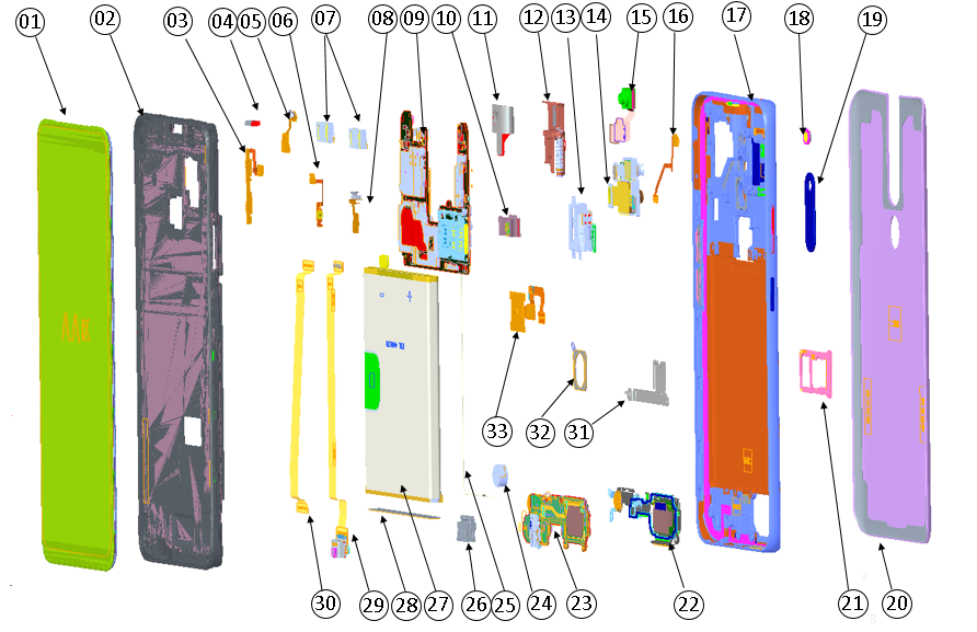
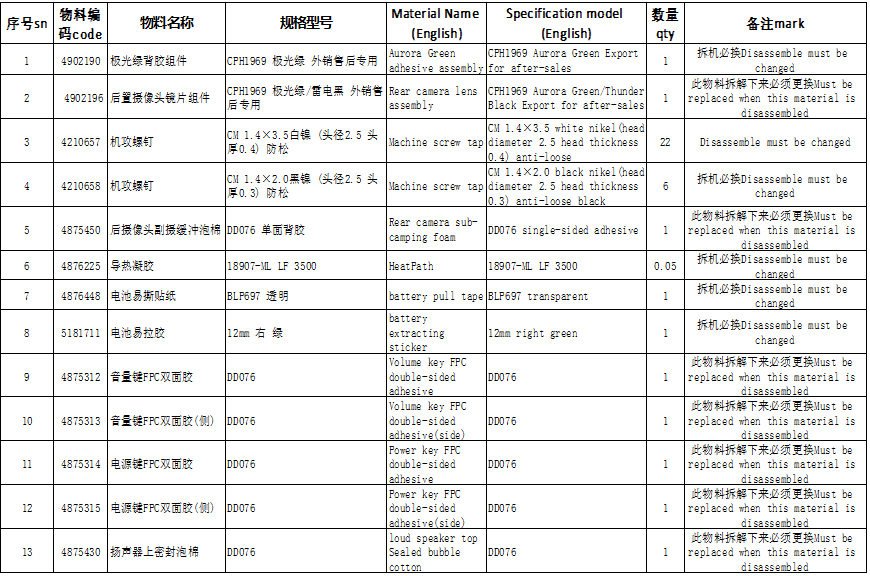
4.2 Exploded map corresponding material table: Note: This table is used only for the name of the annotation. It is not suitable for the preparation of materials. Please refer to the “Price list of Commonly-used Materials and Accessories” for the preparation.
Materials that must be replaced :
5.Disassembly Steps:
| CONTENT | SN | Graphical description | Instructions |
|---|---|---|---|
| Preparation | 1 | 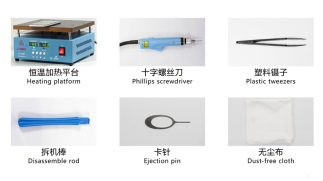 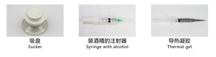 |
|
| 1 |
| ||
| Disassemble the battery cover | 2 | 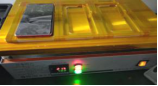 |
|
| Disassemble the bottom cover | 3 | 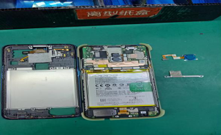 |
|
| Disassemble the battery | 4 |  |
|
| Disassemble the mainboard and rear camera | 5 | 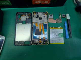 |
|
| Disassemble speaker ,C board ,U board ,RF cable ,motor ,antenna board | 6 | 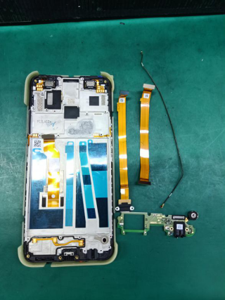 |
|
| Disassemble the front camera and stepper motor ,receiver | 7 | 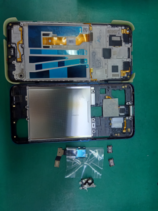 |
|
| Process | SN | Pictures | Operation |
|---|---|---|---|
| Assemble front camera assembly | 1 | 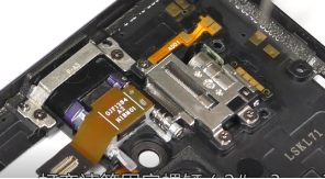 |
|
| Assemble the light sensor | 2 | 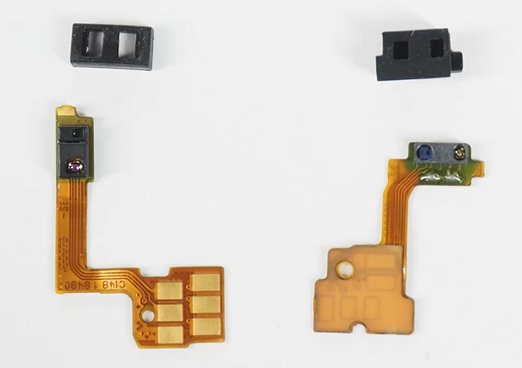 |
|
| Assemble receiver and antenna board | 3 | 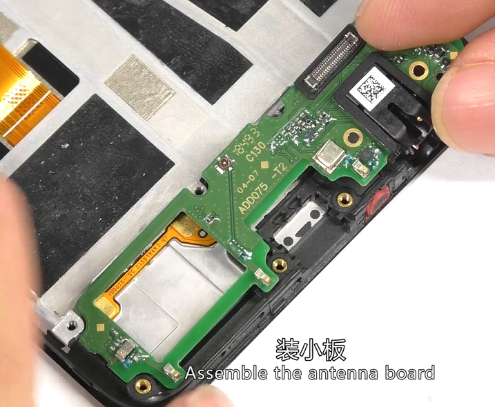 |
|
| Assemble the speaker | 4 | 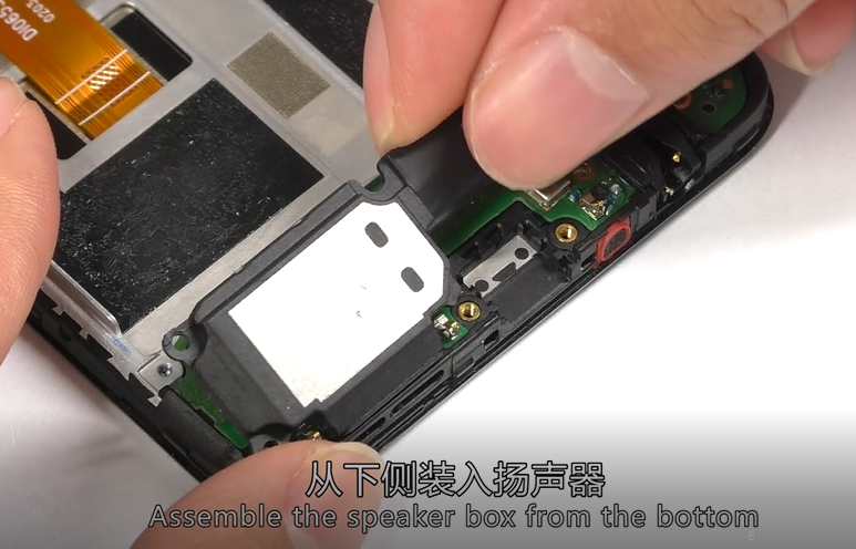 |
|
| Assemble mainboard | 5 |  |
|
| Assemble FPC | 6 |  |
|
| Assemble battery | 7 | 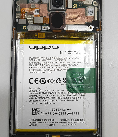 |
|
| Assemble bottom cover assembly | 8 | 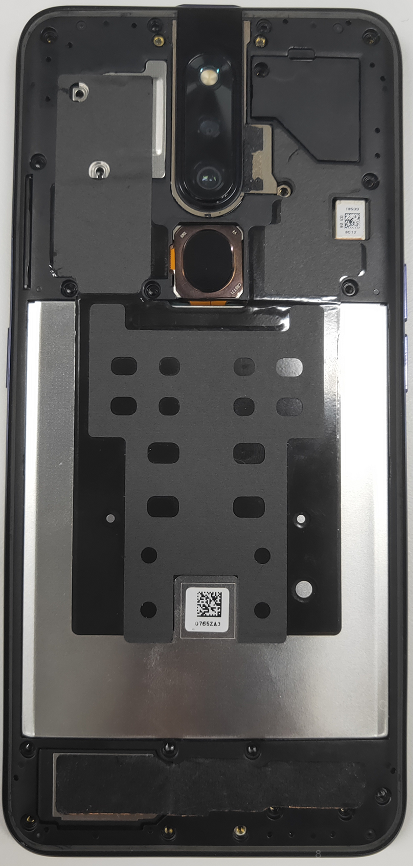 |
|
| assemble battery cover | 9 | 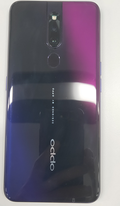 |
|
7.Calibration:
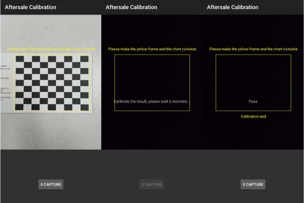
Calibration Path : input *#899# in the dialing interface > Aftersale calibration/ last test in the automatic test ; When the following interface pops up, take a photo with the chart.
Note: Please align the yellow box with the edge of the chart, and then take a Photo. Then, do not operate the phone when the phone enters the computing interface until it display “Pass” with the calibration completed.
Precautions:
1. If the phone sent to the SC is with Poor blurred effect issues in the Portrait Mode, re-calibrate the camera for the user.
2. Re-calibrate the phone for the user once the phone has been disassembled; Or the phone will be with Poor blurred effect issues;
3. If it shows “Fail 69” during calibration, the lens is too far from the chart;
4. If it shows “Fail 70” during calibration, the lens is not parallel to the chart;
5. If it shows “Fail 68” during calibration, the lens is too close from the chart;
8.Post-maintenance functional test:
After the repair is completed, first tested and identified the fault for the user. After the identification is completed, the basic functions of the mobile phone must be tested, and it can be returned to the user after passing the test.
8.1 Visual inspection:
Check whether the mobile phone display screen is dirty or not; the mobile phone has no gaps, cracked shells, cracked keys, scratches, and whether the USB has fallen off etc.
8.2 Functional test path:
Input *#899# in the dial interface > automatic test > function test;
8.3 Testing requirements
| No. | Test Item | Test Requirement |
|---|---|---|
| 1 | Motor hall calibrate | Enter motor Hall calibrate, enter the password "6776", click "Start Calibration", the front camera will rise, then click "Start Test", |
| 2 | Motor test | Enter the motor test and click "Start Test". |
| 3 | LCD test | Click on the screen to switch among red, green, blue, white, black, gray, gray scale , multicolor, and fruit colors, cables, highlights, black spots, etc. |
| 4 | Vibration Test | The motor vibrates for 3 seconds, 1. Listen to the vibration noise. 2. Test whether there is no vibration or vibration weak, If there is the situation above, it is a defective product. |
| 5 | Touch screen auto test | If the interface jumps to the next test, the test is passed |
| 6 | Front camera preview | 1. For the white interface of the camera, detect whether there are black spots, black lines or blurred screen. 2. For the black interface, check whether there are bright spots, white spots or blurred screen; 3. check if the front lift is in place |
| 7 | Rear camera Preview | 1. For the white interface of the camera, detect whether there are black spots, black cables or blurred screen. 2. For the black interface, check whether there are bright spots, white spots or blurred screen; 3. For the interface with words, check whether the focus is clear |
| 8 | Second rear camera Preview | 1. For the white interface of the camera, detect whether there are black spots, black cables or blurred screen. 2. For the black interface, check whether there are bright spots, white spots or blurred screen; 3. For the interface with words, check whether the focus is clear |
| 9 | Echo test |
|
| 10 | Flashlight test | Check the function and color of the flashlight |
| 11 | Flash Charger | If the interface appears “PASS” and the interface automatically jumps to the next test, the VOOC Flash charge test is passed. |
| 12 | Headset in-out plug test | Insert the earphone in the earphone plug test. If the insertion is identified, the earphone test is passed. |
| 13 | Sensor self-test and calibration | Place the mobile phone flat on the desktop, click on the first calibration item. If it shows “PASS”, and automatically jumps to the next test item, it is without failure. |
| 14 | Gyroscope | After entering the test, take the mobile phone to draw the "8" word graphic. After the test OK, PASS will be displayed, and the next test item will be automatically jumped |
| 15 | M Sensor | Shake the phone from the left to the right side in the M Sensor in the test interface. After the test passes, it will automatically jump to the next test item and the M sensor is without failure. |
| 16 | Proximity sensor test | Use the palm to cover the light sensor hole in the Proximity sensor test interface, and the screen will turn green from black. If the test is passed and the interface jump to the next test, the sensor is without failure. |
| 17 | Keypad test | Press the power Key, volume Key one by one. If the interface automatically jumps to the next test item without malfunction (if the Key is stuck or rising), the Key is with failure. |
| 18 | Finger print auto test | Automatic test OK will display PASS, automatically jump to the next test item |
| 19 | Media test | Check whether there is silence, weak sound, noisy sound, broken sound. If there isn’t failure with the speaker, it is passed. |
| 20 | Call test | Call the SIM card operator to check the receiver. If the call is normal without noise, weak sound, the receiver is without failure. |
| 21 | Aftersale calibration | Please make the yellow frame and the chart coincide ,and take a photo ,calibrate the result , please wait a moment ,if calibrate success, will display pass ,calibrate complete |
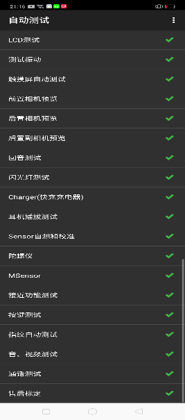
After the above 19 test items are tested, they will prompt to the test result interface. If the test PASS, project will hit “√”; if the test FAIL, project will hit “×”. Items showing "X" need to be clicked again to test, until it is displayed as shown below:
9.Precautions
| ITEM | Disassemble and Assemble Precautions | Fault phenomenon |
|---|---|---|
| 1 | Stepper motor FPC needs to be assembled under the motor | Poor camera lift |
| 2 | Assembly Stepper motor can not press the solder joint position | FPC damage ,and the motor not work |
| 3 | When installing the front camera BTB, pay attention to the fact that the male and female seats are aligned and then gently buckled down. | front camera not open |
| 4 | Disassemble the machine to pay attention to whether the speaker foam is damaged or layered, if layered need to be replaced | Speaker noise |
| 5 | When disassembling the bottom cover, first remove the front BTB bracket, then remove the front camera BTB, careful Front FPC cannot bend and finally disassemble the lower cover. | front camera not open |
| 6 | The light guide column is affected by alcohol. Note that the light guide column can’t have large amount of alcohol. | Abnormal light perception |
| 7 | Do not use alcohol to wipe the front transparent cover; (When there is dirt, use only dry and clean cloth to wipe clean) | Prevent cracking of the cover or failure after repair (acrylic material is not alcohol resistant) |
| 8 | After disassembling the mainboard, immediately clean the thermal gel on the top cover and the mainboard, and do not scrape it onto the shrapnel or gold finger; | Prevent contact failure after the shrapnel is assembled |
| 9 | When assemble the front slider assembly, the front FPC pre-bending must be aligned with the silk screen and pressed with the fingertips; | When there is not sticker well , the front camera will be retracted a number of times, and the FPC will not recover properly and cause the front camera assembly Stuck. |
| 10 | When manually working on the thermal gel, pay attention to the path and method in the disassemble and assembly video; |