A7&AX7 Service Manual-V1
Views: 0 • Likes: 0

Confidential
Content
1.Guidance
2. General Repair Information
3.Purpose
4. Product Overview
5. Disassembly Steps
6. Assembly Steps
7. Functional Test After Maintenance
8. Cautions for Test
9. Defective materials or need scrapped parts after disassmbley
1. Guidance
1.1 Guidance Overview
The purpose of this document is to help OPPO levels 1 and 2 maintenance technicians to carry out service to OPPO products. This Service Manual is to be used only by authorized OPPO maintenance service centers, and the content is confidential. Please note that OPPO provides also other guidance documents (e.g. Technical Service Bulletins) for maintenance service cooperative corporations, therefore, please follow these regularly and comply with the given instructions. While every endeavor has been made to ensure the accuracy of this document, some errors may exist. If you find any error or if you can offer further suggestions, please notify OPPO by using the address below: linjianqi@oppo.com. Please keep in mind also that this documentation is continuously being updated and modified, please keep watching out for the newest version. 1.2. Warnings and Cautions
Please refer to the handset's user guide for instructions relating to operation, service and maintenance including important safety information. Note the following:
Warnings
1. Service centers may be required to install the handset’s vehicle-mounted system in vehicles. Under certain fault conditions, the handset's RF signals may affect the operation of the vehicles' electric power management systems and anti–skid braking systems (ABSs). If necessary, consult the vehicle dealer/manufacturer to determine the immunity of vehicle electronic systems to RF energy.
2. The handset must not be operated in areas likely to contain potentially explosive atmospheres, such as petrol stations, gas stations and blasting areas.
3. Operation of any radio transmitting equipment, including handsets, may interfere with the functionality of the medical devices protected by industrial mechanisms. Consult the manufacturer of the medical devices if necessary. Other electronic equipment may also be subject to interference.
Attention:
1. Maintenance and calibration must be undertaken by qualified technicians only.
2. Ensure all work is carried out at an anti-static workstation and that an anti-static wrist strap is worn.
3. Use only approved materials as specified in the bill of materials (BOM) list.
4. Ensure all components, screws and insulators are correctly re-fitted after
Maintenance and calibration. Ensure all cables and wires are repositioned correctly.
Electrostatic discharge can easily damage the sensitive components of electronic products. Therefore, every service center has to take care of OPPO's ESD protection requirements. Also see ESD Protection Requirements in this Service Manual
2. General Repair Information
※In this section the technician will get some general hints to carry out repairs:
Customer service personnel can download and read product documentation on:Download and read the product guide or user manual on the site:ftp:// :ftp://wxfuwu@172. 16. 103. 212:919
Before starting the repair, you must enter the ESD Protected Area and connect your wristband. Use gloves to avoid corrosion and fingerprints. Protect windows and display screens with a film to avoid dust and scratches. When cleaning the metal pads, you have to use a soft cloth/ESD brush and isopropanol solution. It is not allowed to use an eraser because it scratches the surface and will lead later on to oxidation and corrosion. Mechanical parts (except shielding covers and bent parts), which cannot be repaired in the event of a failure, can only be replaced, if they are not soldered. After removing and maintaining the shielding covers, make sure to replace them with new ones. Otherwise, the high-frequency leakage can have an influence on the device. Always use original OPPO spare parts. Check the soldering joints of the parts, which are concerned regarding the indicated error (e.g. soldered connectors or switches) and re-solder them if necessary (only repair centers that can conduct lead-free soldering). Remove redundant soldering flux after soldering. Assemble the handset with the standard screw torque (see the Introduction of the Service Manual).
Always use your own equipment for testing where you are sure that it works. For complaints about charger function, please test the handset with your own charger to be sure if the handset or charger causes the malfunction. When doing the fault log entries, always note the fault code, which caused the malfunction. The accuracy of this code will be a great help to quality improvement. Also, fill in the replaced part, if needed.
Many service documents are available on the FTP server: ftp://wxfuwu@172. 16. 103. 212:919, which will be notified via email. Please note that the documents shall be updated in time.
3. Purpose
The manual mainly introduces the disassembly method of 18311 and derived models to guide aftersales to repair phones correctly and avoid unnecessary waste.
4. Product Overview
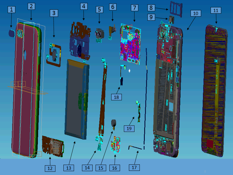
4.1. Phone Structure Explosive View
4.2 Bill of Material
4.3 Material Picture Table
Note: This table is used only for the name of the annotation. It is not suitable for the preparation of inventory. Please refer to the “Price list of Commonly-used Materials and Accessories” for the preparation.
5. Disassembly Steps
5.1 Disassembly Tool
There are the main disassembly tools required as shown below:Electrostatic wristband (electrostatic glove), electricity screwdriver (crosshead: 0.75±0.10kgf),plastic syringe of 2.5ml, disassembling rod, plastic tweezers, protection film, dust-free cloth, ejector pin, etc. 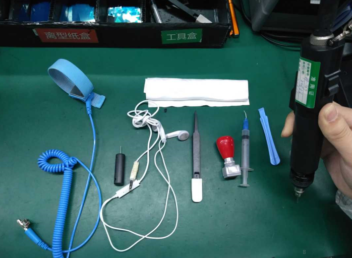 5.2 Ready to work
Select system power key to power off the phone before disassembly.
Methods to power-off: Press the power key and slide to power off.
5.3 Disassembly Steps
(1) Take out the SIM card holder
Use the ejector pin to take out the card holder. 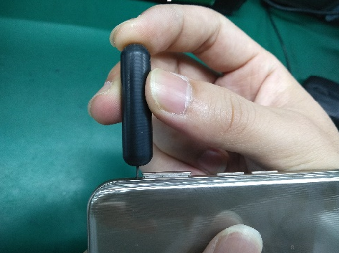
First, remove the battery cover from the lower right corner as shown in below picture with the disassembly rob wrapped by the dust-free cloth (If the battery cover is too tight, use the headphone plug to insert the headphone hole to pry a gap), then use the disassembly rob to insert the slit and open it to the right until it unlocks all the right side hidden buckle, and use the same method to unlock left side hidden buckle. Pay attention not to pull the battery cover too hard to prevent the fingerprint FPC module from breaking. 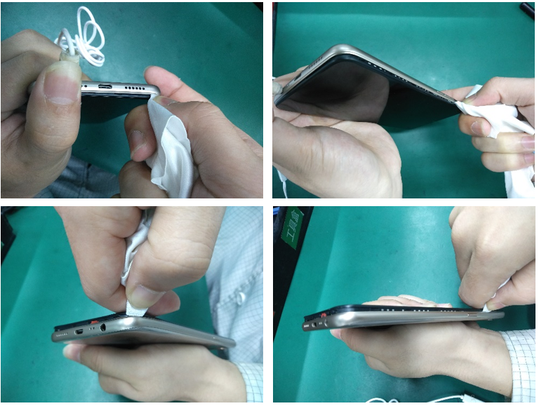
Attention: the appearance of disassembled battery cover should be carefully checked, especially cracks in the position of the side keys and the card holder;
(3) Disassemble the motherboard screws and bracket
Put the handset into the battery protection fixture(make sure that the phone is placed in the fixture properly), use the cross screwdriver to release the remaining 8PCS screws on the motherboard bracket in the counter clockwise direction, Remove the bracket from the lower side of the bracket and put on tray after maintenance marking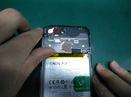
First, pull up the green handle on the right side of the battery, and then pull the green handle to open the easy-tore paper on the right edge of the battery. Then inject around 0.2ML alcohol in each position of the upper and lower handles (red box area) with the 2.5ml syringe. Sideward the phone for 5-10s to make sure that the alcohol penetrates until to the bottom of the easy-tore paper (as shown in below).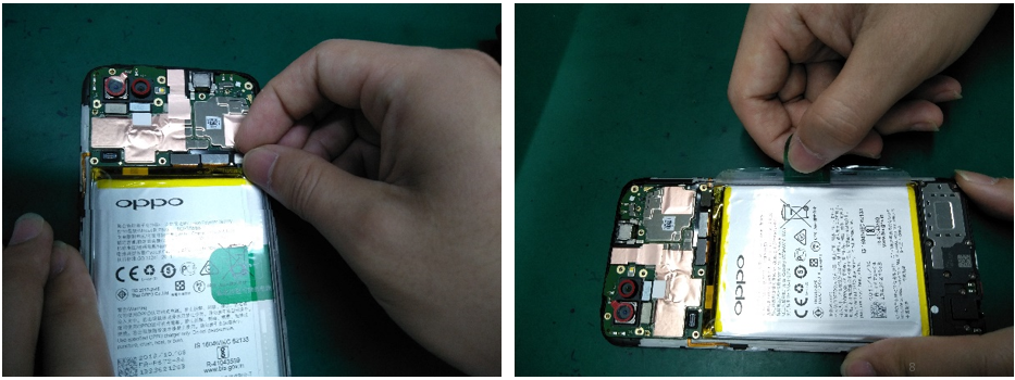
After standing, pull the handle slowly to pull up the battery (Pull up the battery as flat as possible to avoid the battery deformation caused by pulling the battery vertically). Pull the battery together with the easy-tore paper slowly. Make the ”Repaired” mark on the corresponding position of the battery; Use the plastic tweezers to remove the bottom supporting foam; After battery is removed, the double-sided adhesive release paper should be immediately attached to the battery compartment.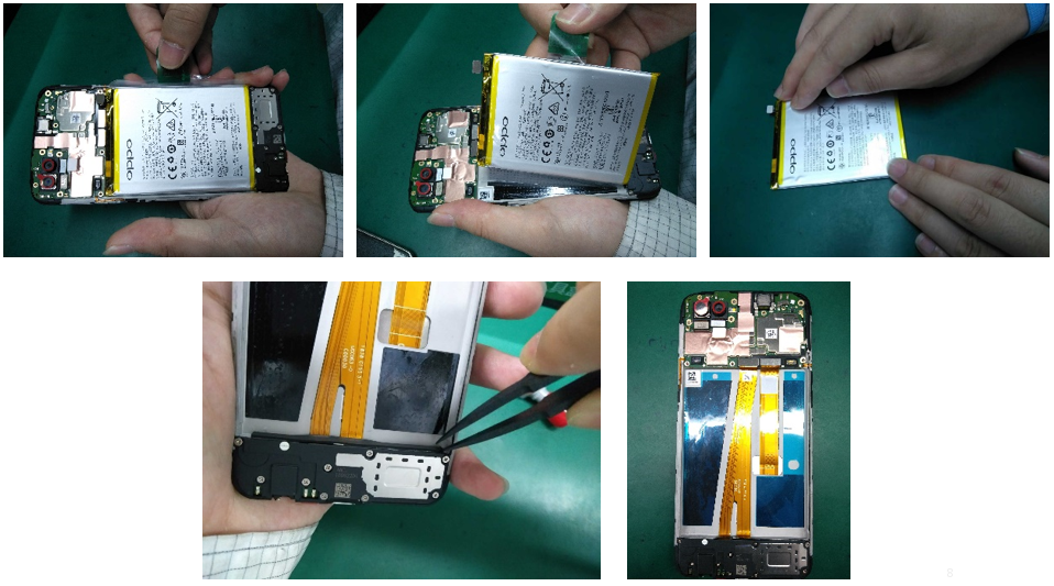
2. The repaired battery cannot be used directly, and it needs to be reattached easy-tore paper;
(5)Disassemble the motherboard and cameras
Remove the RF cable from the groove with plastic tweezers; The cable clip on the motherboard shall be pressed and then gently pull the RF cable out of the cable clip;(The motherboard cannot be removed directly to prevent RF seat dropping. Remove all the BTB seats from the motherboard;
Remove motherboard, then remove the camera and tear apart the copper foil on the front camera surface. A protective film should be attached to the cameras and camera lens to prevent the cameras from being dirty. The motherboard and cameras are respectively marked for maintenance and put into the ESD tray.
(6)Disassemble RF-cable, Speaker, USB FPC, and Antenna board
Use the electric screw driver to disassemble 10 screws as shown in figure 5.3.6.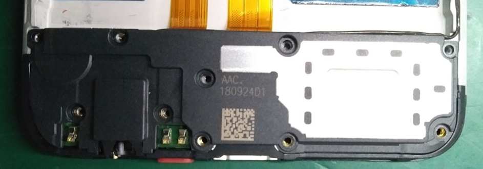
Separate the USB FPC BTB from the antenna board and remove the USB FPC from the motherboard end; Use plastic tweezers to slowly lift the USB FPC from the earphone position to remove it and put it in the tray;
Lift up the antenna board with plastic tweezers from the motor to remove it. Pick up the motor from the gap and remove it with plastic tweezers as shown in figure 5.3.7. 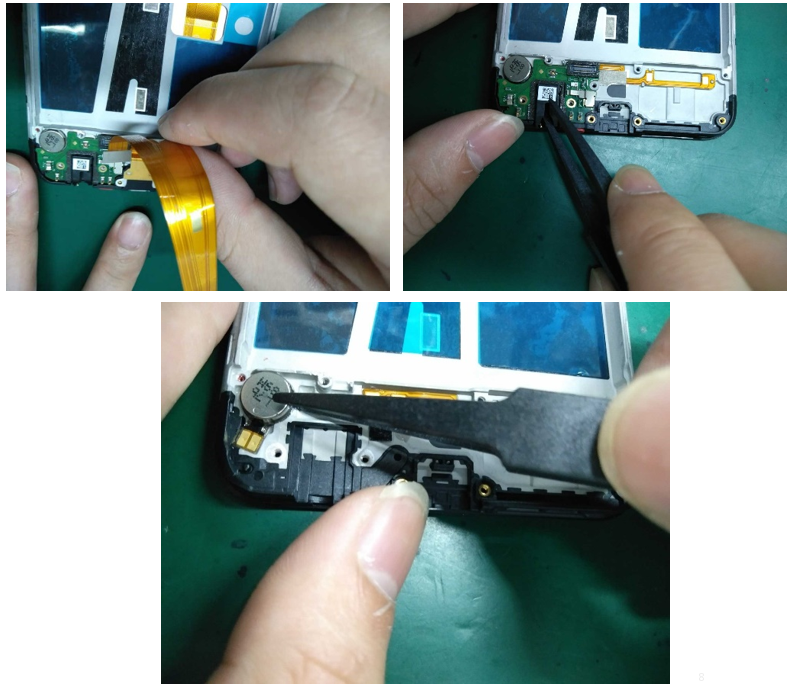
(7)Disassemble the receiver and side keys FPC
Remove the receiver with plastic tweezers from the side of the receiver, as shown in figure 5.3.8.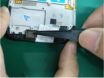
1.Disassembly process:Heat it for 3min in constant temperature platform——Remove the fingerprint module——Clean double sides adhesive residue ——Check the fingerprint appearance check——Test Fingerprint function——Clean the battery cover fingerprint double-sided adhesive——Replace the battery cover fingerprint double-sided adhesive——Check the battery cover appearance——mark the fingerprint module(Dot the back of the fingerprint)——put in tray
2.Attention:
a.Temperature:70°C,Time :3mins
b. In order to avoid tearing the FPC, it is necessary to disassemble the steel sheet which is behind fingerprint from the upper left corner when disassemble fingerprint module;
(9) All materials after disassembly as shown in the below figure.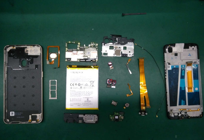
6. Assembly Procedures
6.1 Assemble the side key
First, assemble and fix the Volume Key FPC and Power key FPC on the corresponding location,
Then paste the PET sheet. 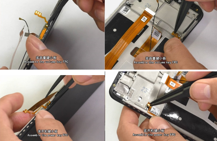 6.2 Assemble the receiver
Assemble the receiver (the shrapnel should be installed in the receiver slot to the left); the body should be assembled into the slot without tilt. 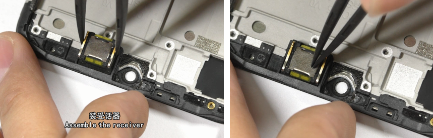 6.3 Assemble the Motor, Antenna Board, Motor, RF Connection cable, USB FPC and the Speaker
Tear off the release paper on the motor, and install it into the slot according to its mark, and press the Motor FPC to avoid tilting; Install the antenna board into the corresponding location; Snap the RF connection cable on the antenna boar end; Assemble and Press the USB FPC connection cable on the BTB buckle on the antenna board; Install the speaker in the corresponding location of screen display assembly. Check whether there is no foreign matter on the Speaker; the assembly needs to be in place without tilt; Snap the speaker screws and paste the soft padding in the battery compartment;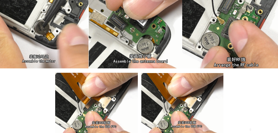 6.4. Assemble the Camera
Snap the BTB buckle of camera on the motherboard in place without tilt or deflection; Paste conductive clothing on back of the front cameras along the graphite flake from the top; The end of conductive clothing cannot be pasted on the graphite flake or the middle frame; the conductive clothing cannot be crinkled or reversed;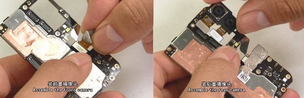 6.5 Assemble the Motherboard
First, insert the motherboard from the right side to the left side into the upper cover buckle, and then put it into the upper cover assembly slot flatly. The motherboard is completely buckled by the upper cover. The motherboard is required to be assembled in place gently. The motherboard can't be tilted, then the card holder should be installed; 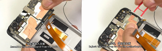 6.6 Snap and smooth the FPC
Snap the main FPC, USB FPC, RF cable BTB connector on the main board end, and then smooth the FPC from bottom to top to make the FPC fit the middle frame. Make the BTB flat without tilt, and the FPC should be closely attached to the middle frame. 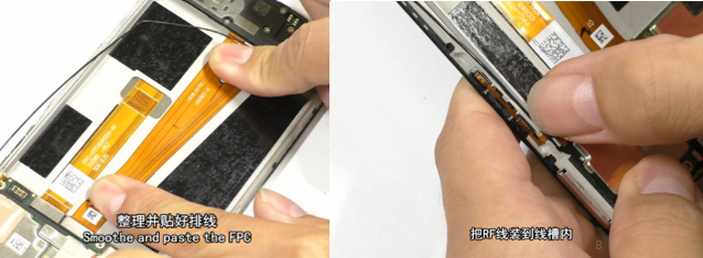 6.7 Assemble the Battery
Make sure there is no foreign matter in the battery compartment, and there is no damage or liquid leakage of battery. Wrap the battery with new easy-tore paper on the battery, and install the battery into the battery compartment after buckling the battery BTB connector;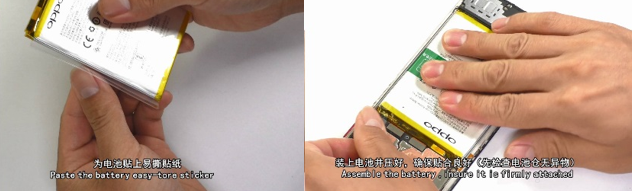 6.8 Assemble the motherboard bracket and screws
Install the motherboard bracket in the upper cover assembly according to the slot (Tear off the release paper if there is any on the bracket ); After disassembling the bracket, lock the screws with the electric screwdriver and make sure that the screws are locked perfectly(without excursion, slippery, excess or omission); 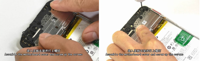 6.9 Assemble the Battery Cover
Take out the pre-installed card holder for fixing motherboard, and assemble the battery cover. Check the appearance to make sure that the cover is snapped; Then, install the card holder. 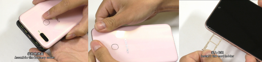 7. Functional Test after Maintenance
After maintenance, identify the faults described by the user and test other functions of the phone. When the phone proves qualified after testing, return it to the user.
7.1 Appearance Detection
Verify whether the handset display screen has abnormalities such as stains, wide gap, cracked shell, cracked key, scratch and whether the USB port falls off.
7.2. Function Detection
7.2.1 Test Requirement
7.2.2. Test Method
1) LCD Test
Inputting *#807# in the dial interface will automatically enter the LCD test of the function test. Click on the screen to switch among red, green, blue, white, black, gray, gray scale , multicolor, and fruit colors, lines, highlights, black spots, etc

After the test is finished, the interface will automatically appear the “Confirm” dialogue box. If the LCD test fails, select “FAIL”. If the LCD test is passed, select “PASS”. The interface will jump to the next test if the result is confirmed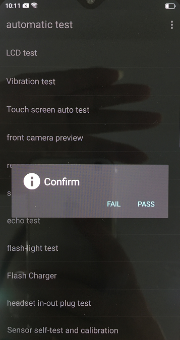 2) Vibration Test
When the motor vibrates for 3 seconds, move the motor close to the ear. Test according to the above table. The “Confirm” dialog box will jump automatically after 3 seconds of the test. Select “PASS” if the test is passed. If there is noisy vibration, no vibration, or weak vibration, select "FAIL";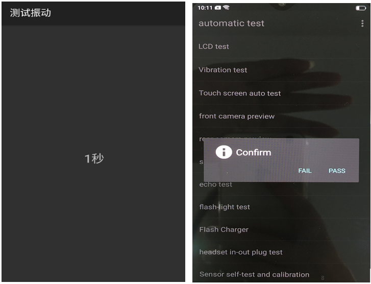 3) Touch Screen Automatic Test
The interface will jump to the touch screen automatic test after the last test was finished, and the mobile phone system will automatically test touch screen.
After the test is passed, it will automatically jump to the next test item; if the test fails, the interface will not jump. Press the return key to enter “Confirm” Dialog box, and select "FAIL";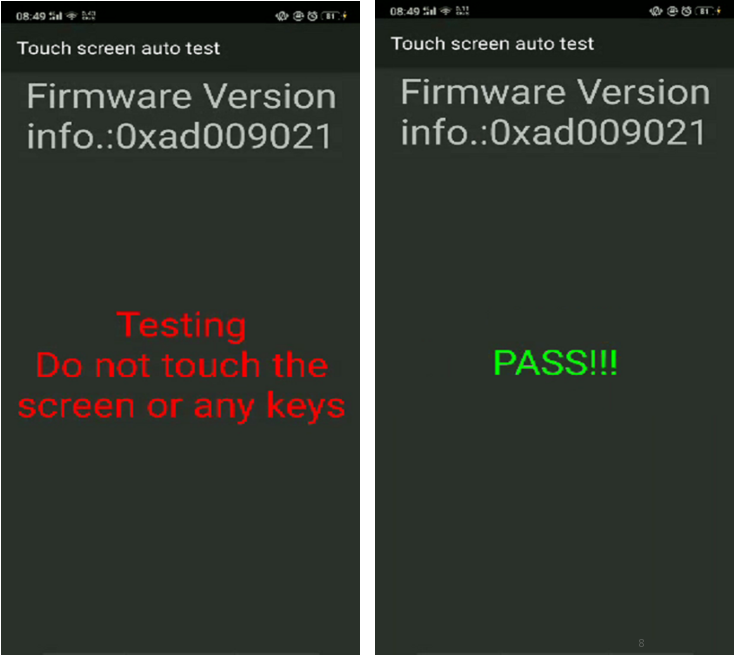 4) Rear camera Detection
After judging the result of the vibration, the Detection interface automatically entered for 5 seconds. Test according to the above test requirements. Judge the test result when the machine enters automatically “Confirm” dialog box after 5 seconds.
5)Rear camera
The Detection interface of rear camera will be automatically entered for 5 seconds after judging the front camera. Test according to the above test requirements. Judge the test result when the machine enters automatically “Confirm” dialog box after 5 seconds.
6) Second rear camera
The Detection interface of sub rear camera will be automatically entered for 5 seconds after judging the main rear camera. Test according to the above test requirements. Judge the test result when the machine enters automatically “Confirm” dialog box after 5 seconds.
7) Flashlight test
The test interface of flashlight will be automatically entered for 5 seconds after judging the sub rear camera. Test according to the above test requirements. Judge the test result when the machine enters automatically “Confirm” dialog box after 5 seconds.
8) Echo test
In the echo test, if “Main MIC” turns gray, the main MIC is being tested.;Blow the air to the MIC hole on the bottom of the phone. If the receiver (earphone) sounds, the test is passed; Then click on the " sub MIC" to test the sub MIC and blow air to the sub MIC hole on the top of the phone. If the speaker sounds, the test is passed. Press the return key to enter the “Confirm” dialog box and judge the result.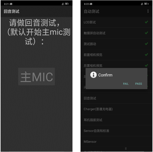 9) VOOC Flash Charge Test
Use the OPPO dedicated VOOC adapter and VOOC Line test. If the test is passed, it will automatically jump to the next test item. If the test fails, the interface will not jump. Press the return key to enter the “Confirm” dialog box and select "FAIL";
10) Earphone Plug Test
Enter the earphone plug-in test with the OPPO earphone and the interface will automatically jump to the next test item. If the test fails, the interface will not jump. Press the return key to enter the “Confirm” dialog box and select "FAIL";
11) Sensor Self-Calibration
When the phone enters into the Sensor self-calibration interface, the phone must be placed on the desk flatly. Then click the first calibration item. After the test is passed, it will automatically jump to the next test item; if the test fails, the interface will not jump. Press the return key to enter “Confirm” Dialog box, and select "FAIL"; 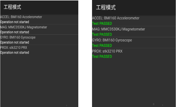 12) M Sensor
Shake the phone from the left to the right side in the M Sensor in the test interface. After the test passes, it will automatically jump to the next test item; if the test fails, the interface will not jump. Press the return key to enter “Confirm” Dialog box, and select "FAIL" 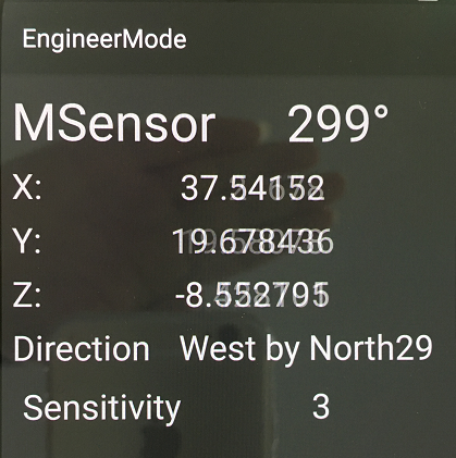 13)Proximity sensor test
Use the palm to cover the light sensor hole in the Proximity sensor test interface, and the screen will turn green from black,After the test passes, it will automatically jump to the next test item; if the test fails, the interface will not jump. Press the return key to enter “Confirm” Dialog box, and select "FAIL";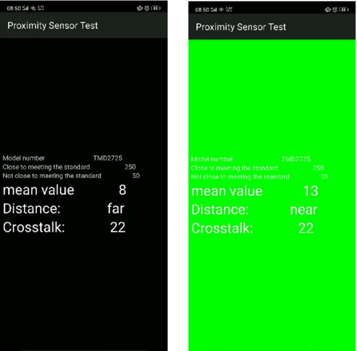 14)Keypad Test
Several machines with visual Keys(like R7s/R11s) can only test 3 Keys: Power Key, Volume Plus Key and volume deduction Key; Machines with physical Keys need to test 6 Keys to be tested which will be identified in the test. After the test passes, it will automatically jump to the next test item; if the test fails, the interface will not jump. Press the return key to enter “Confirm” Dialog box, and select "FAIL";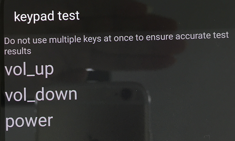 15) Audio& Video Test
Click the 20-4K(-3db)signal” to test the sound in the audio& video test interface. The interface will enter the “Confirm” dialogue box after tested for 5 seconds Then judge the test result;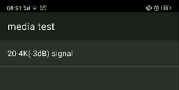 16) Call Test
If the phone has been installed with the operator's SIM card, dial the corresponding operator's phone number. If no card is inserted, call the 112 test (It is recommended to install the sim card to call). Check according to requirements, press the return key to enter “Confirm” dialog box, and select the result of the judgment;
After the above 16 test items are tested, they will prompt to the test result interface. If the test PASS, project will hit “√”; If the test FAIL, project will hit “×”.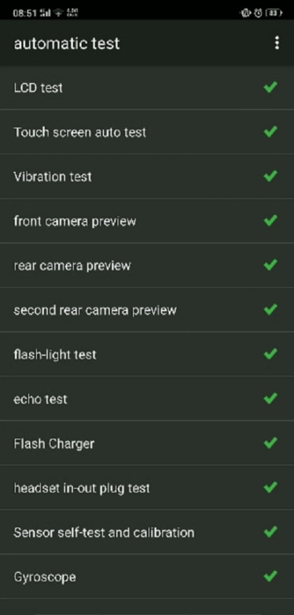 After the above 16 test items are tested, they will prompt to the test result interface. If the test PASS, project will hit “√”; If the test FAIL, project will hit “×”.
8. Cautions for test items
1. Sensory test items require staff to judge the results such as LCD test, vibration test, front camera test, rear camera test, flashlight test, echo test, audio test, and call test. Therefore, the results must be judge according to test requirements
2. After the test is passed, the interface will automatically return to the "Confirm" dialog box. Only the echo test and call test need to press the return key to enter the "Confirm" dialog box.
3. It is forbidden to press the return key while the test has not finished yet and judge the result in advance.
9. The damaged materials or need replace materials after disassembly
(1) All accessories, including double-sided adhesive, graphite sheet, copper foil, conductive cloth, foam, once disassembled, cannot be reused;
(2) All appearance parts must be checked after being removed and confirmed OK before they can be used;
(3) All electronic components must be tested before they can be used normally;
(4) Disassembly parts shall be marked with maintenance sign, and damaged products shall be distinguished from normal parts to avoid mixing;
| NO. | Material name | Model specification | Unit | Number |
| 1 | Camera Lens | CC065 black glass GG5 | PCS | 1 |
| 2 | Battery cover | CC060 blue with accessories | PCS | 1 |
| 3 | Fingerprints sensor module | FPC1023+2060 11.8×9×1.14 BTB CC065 A181 Glass Blue Bezel | PCS | 1 |
| 4 | Mainboard bracket | CC065 black with accessories | PCS | 1 |
| 5 | camera module | S5K3L6+GC2375HW 13M+2M 19.25×11×4.44 5P+3P BTB 110A | PCS | 1 |
| 6 | camera | IMX371-AAJH5-C 16M 7.6x7.2x4.92 5P BTB A16N15D | PCS | 1 |
| 7 | PCB semi-finished | 2CC063-0 CC063 4GB 64GB | PCS | 1 |
| 8 | SIM card holder. | CC065 Blue | PCS | 1 |
| 9 | Receiver | 50mW 32Ω 10×8.5×2 plate spring G | PCS | 1 |
| 10 | Upper cover | CC065 Black with cushions | PCS | 1 |
| 11 | Full fit screen | PD062JA-05A | PCS | 1 |
| 12 | Speaker | 1W 8Ω 66.5×25.6×3.6 BOX A | PCS | 1 |
| 13 | Lithium Battery | @4100/3.85V/0.7C BLP673 416587 FA I724 | PCS | 1 |
| 14 | FPC semi-finished product | UCC063-0-Patch CC063 | PCS | 1 |
| 15 | Vibration Motor | 8mm 3.0mm pin inversion 0.1myla_HZF 3V 31Ω±15% WT | PCS | 1 |
| 16 | PCB semi-finished product | ACC063-0 CC063 Black | PCS | 1 |
| 17 | RF Connection Line | 50Ω 175.5mm FCCAL0690176A0(Φ0.64) | PCS | 1 |
| 18 | FPC semi-finished product | PCC063-0-Patch CC063 | PCS | 1 |
| 19 | FPC semi-finished product | VCC063-SD-PatchCC063 | PCS | 1 |
| N0. | Material Code | Material Name | Physical Picture |
|---|---|---|---|
| 1 | 4902021 4902022 4902023 4902024 4902025 4902026 |
Battery cover assembly | 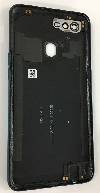 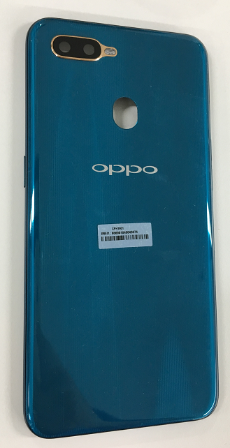 |
| 2 | 4902020 | Display assembly | 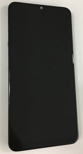 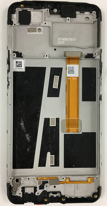 |
| 3 | 4902027 4902028 4902029 4902030 4902031 4902032 4902033 |
Motherboard assembly |  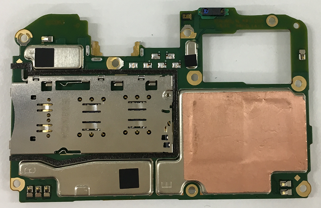 |
| 4 | 4902036 | Camera lens assembly | 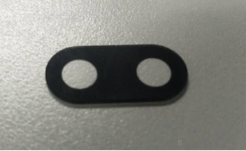 |
| 5 | 4902034 | Power key FPC assembly | 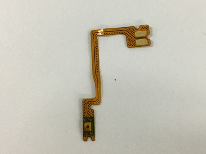 |
| 6 | 4902035 | Volume key FPC assembly | 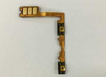 |
| 7 | 4901709 | Battery assembly | 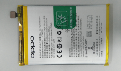 |
| 8 | 4962599 | USB semi-finished product FPC | 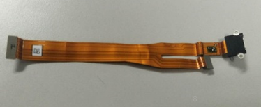 |
| 9 | 8511078 | Speaker | 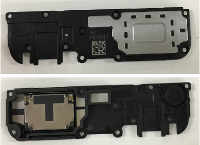 |
| 10 | 9490677 | Front camera | 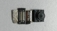 |
| 11 | 8520149 | Receiver | 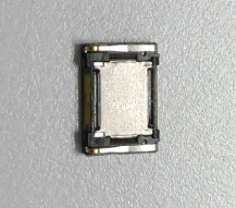 |
| 12 | 9490673 | Rear camera | 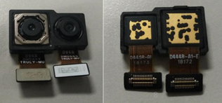 |
| 13 | 2180612 | RF connection cable | 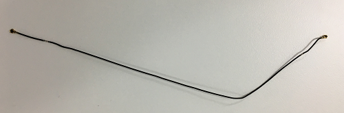 |
| 14 | 4875070 | USB silicone sleeve | 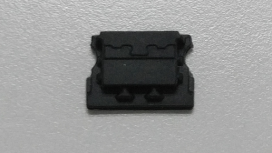 |
| 15 | 2929103 | Motherboard bracket | 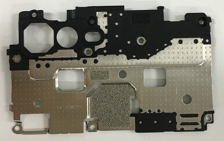 |
| 16 | 2929215 2929117 2929249 2929253 |
SIM card holder. | 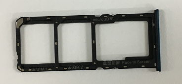 |
| 17 | 8710133 | Vibration motor | 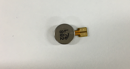 |
| 18 | 4962727 4962638 |
Semi-finished PCB | 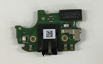 |
5. Disassembly Steps
5.1 Disassembly Tool
There are the main disassembly tools required as shown below:Electrostatic wristband (electrostatic glove), electricity screwdriver (crosshead: 0.75±0.10kgf),plastic syringe of 2.5ml, disassembling rod, plastic tweezers, protection film, dust-free cloth, ejector pin, etc.
Select system power key to power off the phone before disassembly.
Methods to power-off: Press the power key and slide to power off.
5.3 Disassembly Steps
(1) Take out the SIM card holder
Use the ejector pin to take out the card holder.
Figure 5.3.1
(2)Remove the battery coverFirst, remove the battery cover from the lower right corner as shown in below picture with the disassembly rob wrapped by the dust-free cloth (If the battery cover is too tight, use the headphone plug to insert the headphone hole to pry a gap), then use the disassembly rob to insert the slit and open it to the right until it unlocks all the right side hidden buckle, and use the same method to unlock left side hidden buckle. Pay attention not to pull the battery cover too hard to prevent the fingerprint FPC module from breaking.
Figure 5.3.2
After disassembling the battery cover, the rear cameras should be wrapped with protective film in time to prevent cameras from being dirty. The camera lens inside the battery cover should be protected with textured paper, and the back of the battery cover is protected by low viscosity protective film. Attention: the appearance of disassembled battery cover should be carefully checked, especially cracks in the position of the side keys and the card holder;
(3) Disassemble the motherboard screws and bracket
Put the handset into the battery protection fixture(make sure that the phone is placed in the fixture properly), use the cross screwdriver to release the remaining 8PCS screws on the motherboard bracket in the counter clockwise direction, Remove the bracket from the lower side of the bracket and put on tray after maintenance marking
Figure 5.3.3
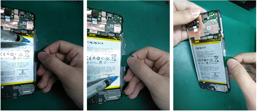
(4) Disassemble the batteryFirst, pull up the green handle on the right side of the battery, and then pull the green handle to open the easy-tore paper on the right edge of the battery. Then inject around 0.2ML alcohol in each position of the upper and lower handles (red box area) with the 2.5ml syringe. Sideward the phone for 5-10s to make sure that the alcohol penetrates until to the bottom of the easy-tore paper (as shown in below).
Figure 5.3.4
After standing, pull the handle slowly to pull up the battery (Pull up the battery as flat as possible to avoid the battery deformation caused by pulling the battery vertically). Pull the battery together with the easy-tore paper slowly. Make the ”Repaired” mark on the corresponding position of the battery; Use the plastic tweezers to remove the bottom supporting foam; After battery is removed, the double-sided adhesive release paper should be immediately attached to the battery compartment.
Figure 5.3.5
Attention: 1.After battery is removed, it needs to be put into the designated special tray; Make “M” marks on the defective spare parts, and make “Y” mark on the good defective spare parts; 2. The repaired battery cannot be used directly, and it needs to be reattached easy-tore paper;
(5)Disassemble the motherboard and cameras
Remove the RF cable from the groove with plastic tweezers; The cable clip on the motherboard shall be pressed and then gently pull the RF cable out of the cable clip;(The motherboard cannot be removed directly to prevent RF seat dropping. Remove all the BTB seats from the motherboard;
Remove motherboard, then remove the camera and tear apart the copper foil on the front camera surface. A protective film should be attached to the cameras and camera lens to prevent the cameras from being dirty. The motherboard and cameras are respectively marked for maintenance and put into the ESD tray.
(6)Disassemble RF-cable, Speaker, USB FPC, and Antenna board
Use the electric screw driver to disassemble 10 screws as shown in figure 5.3.6.
Figure 5.3.6
Remove the speaker from the upper left corner, then remove the RF cable from the groove and gently pull up the RF cable from the antenna board. The way to remove RF cable of antenna board is same with that of the motherboard (The motherboard cannot be directly pulled out to prevent RF seat dropping).Separate the USB FPC BTB from the antenna board and remove the USB FPC from the motherboard end; Use plastic tweezers to slowly lift the USB FPC from the earphone position to remove it and put it in the tray;
Lift up the antenna board with plastic tweezers from the motor to remove it. Pick up the motor from the gap and remove it with plastic tweezers as shown in figure 5.3.7.
Figure 5.3.7
(7)Disassemble the receiver and side keys FPC
Remove the receiver with plastic tweezers from the side of the receiver, as shown in figure 5.3.8.
Figure 5.3.8
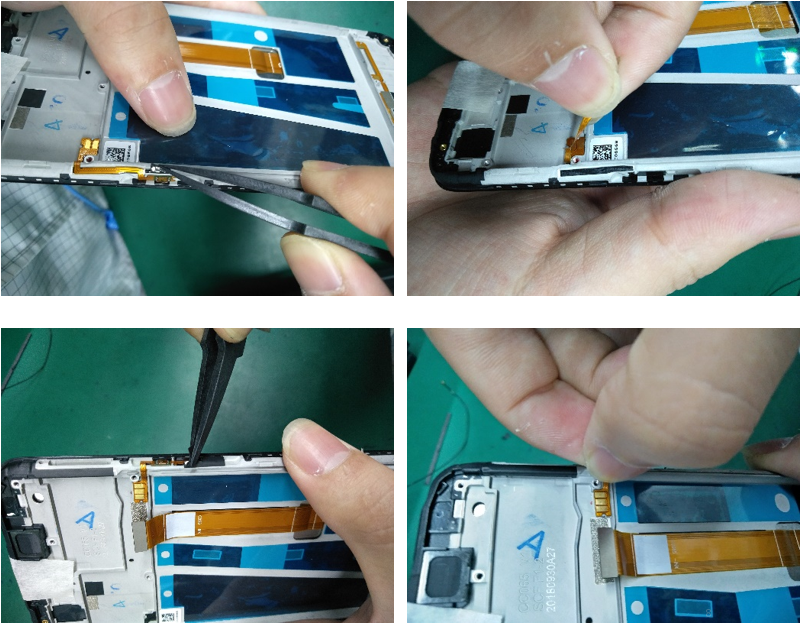
After the PET sheet is torn off, lift the FPC with plastic tweezers from the gap of the FPC, and then slowly tear the FPC off, as shown in figure 5.3.9 below;
Figure 5.3.9
(8)Disassemble the fingerprint module1.Disassembly process:Heat it for 3min in constant temperature platform——Remove the fingerprint module——Clean double sides adhesive residue ——Check the fingerprint appearance check——Test Fingerprint function——Clean the battery cover fingerprint double-sided adhesive——Replace the battery cover fingerprint double-sided adhesive——Check the battery cover appearance——mark the fingerprint module(Dot the back of the fingerprint)——put in tray
2.Attention:
a.Temperature:70°C,Time :3mins
b. In order to avoid tearing the FPC, it is necessary to disassemble the steel sheet which is behind fingerprint from the upper left corner when disassemble fingerprint module;
(9) All materials after disassembly as shown in the below figure.
Figure 5.3.10
6. Assembly Procedures
6.1 Assemble the side key
First, assemble and fix the Volume Key FPC and Power key FPC on the corresponding location,
Then paste the PET sheet.
Assemble the receiver (the shrapnel should be installed in the receiver slot to the left); the body should be assembled into the slot without tilt.
Tear off the release paper on the motor, and install it into the slot according to its mark, and press the Motor FPC to avoid tilting; Install the antenna board into the corresponding location; Snap the RF connection cable on the antenna boar end; Assemble and Press the USB FPC connection cable on the BTB buckle on the antenna board; Install the speaker in the corresponding location of screen display assembly. Check whether there is no foreign matter on the Speaker; the assembly needs to be in place without tilt; Snap the speaker screws and paste the soft padding in the battery compartment;
Snap the BTB buckle of camera on the motherboard in place without tilt or deflection; Paste conductive clothing on back of the front cameras along the graphite flake from the top; The end of conductive clothing cannot be pasted on the graphite flake or the middle frame; the conductive clothing cannot be crinkled or reversed;
First, insert the motherboard from the right side to the left side into the upper cover buckle, and then put it into the upper cover assembly slot flatly. The motherboard is completely buckled by the upper cover. The motherboard is required to be assembled in place gently. The motherboard can't be tilted, then the card holder should be installed;
Snap the main FPC, USB FPC, RF cable BTB connector on the main board end, and then smooth the FPC from bottom to top to make the FPC fit the middle frame. Make the BTB flat without tilt, and the FPC should be closely attached to the middle frame.
Make sure there is no foreign matter in the battery compartment, and there is no damage or liquid leakage of battery. Wrap the battery with new easy-tore paper on the battery, and install the battery into the battery compartment after buckling the battery BTB connector;
Install the motherboard bracket in the upper cover assembly according to the slot (Tear off the release paper if there is any on the bracket ); After disassembling the bracket, lock the screws with the electric screwdriver and make sure that the screws are locked perfectly(without excursion, slippery, excess or omission);
Take out the pre-installed card holder for fixing motherboard, and assemble the battery cover. Check the appearance to make sure that the cover is snapped; Then, install the card holder.
After maintenance, identify the faults described by the user and test other functions of the phone. When the phone proves qualified after testing, return it to the user.
7.1 Appearance Detection
Verify whether the handset display screen has abnormalities such as stains, wide gap, cracked shell, cracked key, scratch and whether the USB port falls off.
7.2. Function Detection
7.2.1 Test Requirement
| No. | Test Item | Test Requirement |
| 1 | LCD test | Click on the screen to switch among red, green, blue, white, black, gray, gray scale , multicolor, and fruit colors, lines, highlights, black spots, etc. |
| 2 | Vibration Test | 1.Get ear close to check whether there is noisy vibration 2.Check there is no vibration, or weak vibration |
| 3 | Touch screen test | If the interface jumps to the next test, the test is passed |
| 4 | Front camera preview | 1. For the white interface of the camera, detect whether there are black spots, black lines or blurred screen. 2. For the black interface, check whether there are bright spots, white spots or blurred screen; |
| 5 | Rear camera preview | 1. For the white interface of the camera, detect whether there are black spots, black lines or blurred screen. 2. For the black interface, check whether there are bright spots, white spots or blurred screen; 3. For the interface with words, check whether the focus is clear |
| 6 | Second rear camera preview | 1. For the white interface of the camera, detect whether there are black spots, black lines or blurred screen. 2. For the black interface, check whether there are bright spots, white spots or blurred screen; 3. For the interface with words, check whether the focus is clear |
| 7 | Echo test |
|
| 8 | Flash-light test | Check the function and color of the flashlight |
| 9 | Flash charger | If the interface appears “PASS” and the interface automatically jumps to the next test, the VOOC Flash charge test is passed. |
| 10 | Handset in-out plug test | Insert the earphone in the earphone plug test. If the insertion is identified, the earphone test is passed. |
| 11 | Sensor Self-Calibration | Place the mobile phone flat on the desktop, click on the first calibration item. If it shows “PASS”, and automatically jumps to the next test item, it is without failure. |
| 12 | M Sensor | Shake the phone from the left to the right side in the M Sensor in the test interface. After the test passes, it will automatically jump to the next test item and the M sensor is without failure. |
| 13 | Proximity-sensor test | Use the palm to cover the light sensor hole in the Proximity sensor test interface, and the screen will turn green from black. If the test is passed and the interface jump to the next test, the sensor is without failure. |
| 14 | Key test | Press the power Key, volume Key one by one. If the interface automatically jumps to the next test item without abnormal feeling (Key stuck or rising), the Key is with failure. |
| 15 | Audio test | Check whether there is silence, weak sound, noisy sound, broken sound. If there isn’t failure with the speaker, it is passed. |
| 16 | Call test | Call the SIM card operator to check the receiver. If the call is normal without noise, weak sound, the receiver is without failure. |
1) LCD Test
Inputting *#807# in the dial interface will automatically enter the LCD test of the function test. Click on the screen to switch among red, green, blue, white, black, gray, gray scale , multicolor, and fruit colors, lines, highlights, black spots, etc
After the test is finished, the interface will automatically appear the “Confirm” dialogue box. If the LCD test fails, select “FAIL”. If the LCD test is passed, select “PASS”. The interface will jump to the next test if the result is confirmed
When the motor vibrates for 3 seconds, move the motor close to the ear. Test according to the above table. The “Confirm” dialog box will jump automatically after 3 seconds of the test. Select “PASS” if the test is passed. If there is noisy vibration, no vibration, or weak vibration, select "FAIL";
The interface will jump to the touch screen automatic test after the last test was finished, and the mobile phone system will automatically test touch screen.
After the test is passed, it will automatically jump to the next test item; if the test fails, the interface will not jump. Press the return key to enter “Confirm” Dialog box, and select "FAIL";
After judging the result of the vibration, the Detection interface automatically entered for 5 seconds. Test according to the above test requirements. Judge the test result when the machine enters automatically “Confirm” dialog box after 5 seconds.
5)Rear camera
The Detection interface of rear camera will be automatically entered for 5 seconds after judging the front camera. Test according to the above test requirements. Judge the test result when the machine enters automatically “Confirm” dialog box after 5 seconds.
6) Second rear camera
The Detection interface of sub rear camera will be automatically entered for 5 seconds after judging the main rear camera. Test according to the above test requirements. Judge the test result when the machine enters automatically “Confirm” dialog box after 5 seconds.
7) Flashlight test
The test interface of flashlight will be automatically entered for 5 seconds after judging the sub rear camera. Test according to the above test requirements. Judge the test result when the machine enters automatically “Confirm” dialog box after 5 seconds.
8) Echo test
In the echo test, if “Main MIC” turns gray, the main MIC is being tested.;Blow the air to the MIC hole on the bottom of the phone. If the receiver (earphone) sounds, the test is passed; Then click on the " sub MIC" to test the sub MIC and blow air to the sub MIC hole on the top of the phone. If the speaker sounds, the test is passed. Press the return key to enter the “Confirm” dialog box and judge the result.
Use the OPPO dedicated VOOC adapter and VOOC Line test. If the test is passed, it will automatically jump to the next test item. If the test fails, the interface will not jump. Press the return key to enter the “Confirm” dialog box and select "FAIL";
10) Earphone Plug Test
Enter the earphone plug-in test with the OPPO earphone and the interface will automatically jump to the next test item. If the test fails, the interface will not jump. Press the return key to enter the “Confirm” dialog box and select "FAIL";
11) Sensor Self-Calibration
When the phone enters into the Sensor self-calibration interface, the phone must be placed on the desk flatly. Then click the first calibration item. After the test is passed, it will automatically jump to the next test item; if the test fails, the interface will not jump. Press the return key to enter “Confirm” Dialog box, and select "FAIL";
Shake the phone from the left to the right side in the M Sensor in the test interface. After the test passes, it will automatically jump to the next test item; if the test fails, the interface will not jump. Press the return key to enter “Confirm” Dialog box, and select "FAIL"
Use the palm to cover the light sensor hole in the Proximity sensor test interface, and the screen will turn green from black,After the test passes, it will automatically jump to the next test item; if the test fails, the interface will not jump. Press the return key to enter “Confirm” Dialog box, and select "FAIL";
Several machines with visual Keys(like R7s/R11s) can only test 3 Keys: Power Key, Volume Plus Key and volume deduction Key; Machines with physical Keys need to test 6 Keys to be tested which will be identified in the test. After the test passes, it will automatically jump to the next test item; if the test fails, the interface will not jump. Press the return key to enter “Confirm” Dialog box, and select "FAIL";
Click the 20-4K(-3db)signal” to test the sound in the audio& video test interface. The interface will enter the “Confirm” dialogue box after tested for 5 seconds Then judge the test result;
If the phone has been installed with the operator's SIM card, dial the corresponding operator's phone number. If no card is inserted, call the 112 test (It is recommended to install the sim card to call). Check according to requirements, press the return key to enter “Confirm” dialog box, and select the result of the judgment;
After the above 16 test items are tested, they will prompt to the test result interface. If the test PASS, project will hit “√”; If the test FAIL, project will hit “×”.
8. Cautions for test items
1. Sensory test items require staff to judge the results such as LCD test, vibration test, front camera test, rear camera test, flashlight test, echo test, audio test, and call test. Therefore, the results must be judge according to test requirements
2. After the test is passed, the interface will automatically return to the "Confirm" dialog box. Only the echo test and call test need to press the return key to enter the "Confirm" dialog box.
3. It is forbidden to press the return key while the test has not finished yet and judge the result in advance.
9. The damaged materials or need replace materials after disassembly
| Materials that need to be replace after disassembly | |
| Battery bottom cushion | Easy-tore paper for battery |
| Camera copper sticker(front) | |
(1) All accessories, including double-sided adhesive, graphite sheet, copper foil, conductive cloth, foam, once disassembled, cannot be reused;
(2) All appearance parts must be checked after being removed and confirmed OK before they can be used;
(3) All electronic components must be tested before they can be used normally;
(4) Disassembly parts shall be marked with maintenance sign, and damaged products shall be distinguished from normal parts to avoid mixing;
Ad
Sponsored Deals
Advertisement · Hand-picked offers, refreshed regularly
These are paid/affiliate advertisements from our partner store and are not related to OPPO or OPPO spare parts.
Related Articles
Ad
Sponsored Deals
Advertisement · Hand-picked offers, refreshed regularly
These are paid/affiliate advertisements from our partner store and are not related to OPPO or OPPO spare parts.