A5s/AX5s Service Manual-V1
Views: 3 • Likes: 0

Confidential
Contents
1. Guidance
2. General Repair Information
3. Product Overview
4. Exploded View of Phone’s Structure
5. Disassemble Steps
6. Assemble Steps
7. Calibration
8. Function Test
9. Cautions
1. Guidance
The purpose of this document is to help OPPO level1 and level 2 maintenance engineers to carry out service to OPPO products. This Service Manual is to be used only by authorized OPPO maintenance service centers, and the content shall be keep in confidential. Please note that OPPO provides also other guidance documents (e.g. Technical Service Bulletins) for maintenance service cooperative corporations, therefore, please follow these regularly and comply with the given instructions. While every endeavor has been made to ensure the accuracy of this document, some errors may exist. If you find any error or if you can offer further suggestions, please notify OPPO by using the address below: zhouyangguang@oppo.com.
Please keep in mind also that this document is continuously being updated and modified, please keep watching out for the newest version.
1.1 Warnings
1. Service centers may be required to install the handset's vehicle-mounted system in vehicles. Under certain fault conditions, the handset's RF signals may affect the operation of the vehicles' electric power management systems and anti–skid braking systems (ABSs). If necessary, consult the vehicle dealer/manufacturer to determine the immunity of vehicle electronic systems to RF energy.
2. The handset must not be operated in areas likely to contain potentially explosive atmospheres, such as petrol stations, gas stations and blasting areas.
3. Operation of any radio transmitting equipment, including handsets, may interfere with the functionality of the medical devices protected by industrial mechanisms. Consult the manufacturer of the medical device if necessary. Other electronic equipment may also be subject to interference.
1.2 Cautions
1. Maintenance and calibration must be undertaken by qualified technicians only.
2. Ensure all work is carried out at an anti-static workstation and that an anti-static wrist strap is worn.
3. Use only approved materials as specified in the bill of materials (BOM) list.
4. Ensure all assembly, screws and insulators are correctly re-fitted after maintenance and calibration. Ensure all cables and wires are repositioned correctly.
Electrostatic discharge can easily damage the sensitive assembly of electronic products. Therefore, every service center has to take care of OPPO's ESD protection requirements. Also see ESD Protection Requirements in this Service Manual
2. General Repair Information
※In this section the technician will get some general hints to carry out repairs:
Customer service personnel can download and read product documentation on:Download and read the product guide or user manual on the site:ftp://wxfuwu@172. 16. 103. 212:919
Before starting the repair, you must enter the ESD Protected Area and connect your wristband. Use gloves to avoid corrosion and fingerprints. Protect windows and display screens with a film to avoid dust and scratches. When cleaning the metal pads, you have to use a soft cloth/ESD brush and isopropanol solution. It is not allowed to use an eraser because it scratches the surface and will lead later on to oxidation and corrosion. Mechanical parts (except shielding covers and bent parts), which cannot be repaired in the event of a failure, can only be replaced, if they are not soldered. After removing and maintaining the shielding covers, make sure to replace them with new ones. Otherwise, the high-frequency leakage can have an influence on the device. Always use original OPPO spare parts. Check the soldering joints of the parts, which are concerned regarding the indicated error (e.g. soldered connectors or switches) and re-solder them if necessary (only repair centers that can conduct lead-free soldering). Remove redundant soldering flux after soldering. Assemble the handset with the standard screw torque (see the Introduction of the Service Manual).
Always use your own equipment for testing where you are sure that it works. For complaints about charger function, please test the handset with your own charger to be sure if the handset or charger causes the malfunction. When doing the fault log entries, always note the fault code, which caused the malfunction. The accuracy of this code will be a great help to quality improvement. Also, fill in the replaced part, if needed.
Many service documents are available on the FTP server: ftp://wxfuwu@172. 16. 103. 212:919, which will be notified via email. Please note that the documents shall be updated in time.
3. Product Overview
3.1. Product Introduction
| Parameter | Specification | |
| Screen | Screen | Screen Screen 6.2 inch 1520*720 a-si / Corning Gorilla Glass 3 |
| Operating System | Operating System | Android 8.1 + ColorOS 5.2 |
| CPU | CPU | Mediatek MT6765 Helio P35 (12nm) Octa-core (4x2.3 GHz Cortex-A53 & 4x1.8 GHz Cortex-A53) |
| Memory | RAM | 4GB/3GB/2GB |
| ROM | 32GB/64GB | |
| Camera | Front | 8M |
| Rear | 13M+2M | |
| Network | Network Edition | 4G+ |
| Network Model | GSM,WCDMA,TD-LTE,LTE FDD | |
| Support Band | GSM: 850/900/1800/1900MHz WCDMA: 850/900/2100MHz FDD-LTE: Bands 1/3/5/8 TD-LTE: Bands 38/40/41(2535-2655MHz) |
|
| Battery | Capacity | 4230mAh |
| Data | Bluetooth | BT4.2 |
| WIFI | WLAN 2.4G,WLAN 5.1G,WLAN Display | |
| Sensor | L-sensor, G-sensor, Proximity Sensor, Acceleration sensor, Magnetic induction | |
| SIM Card | Double Nano card | |
| T card External Memory | 256GB | |
| Earphone | 3.5mm American standard headphone jack | |
| Adapter | 5V2A | |
| USB | 1m USB plug/Micro 5P DL139 white with OPPO packing(white and green/with shielding shell); Recyclable mark with CE logo | |
| Other Features | Fingerprint Unlock | |
4. Exploded View of Phone’s Structure
4.1. Machine decomposition diagram
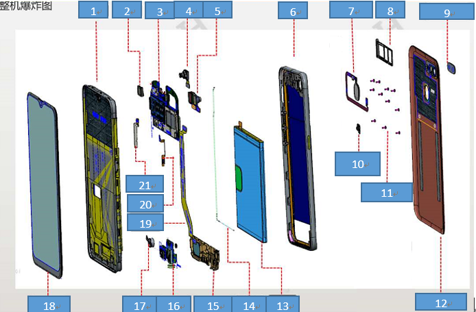
4.2 Exploded map corresponding material table:
| NO | Material name | Picture | specifications | Quantity | Unit |
|---|---|---|---|---|---|
| 1 | Screen cover assembly | 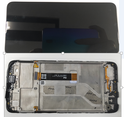 |
Display assembly | 1 | PCS |
| Upper cover | 1 | PCS | |||
| 2 | Receiver | 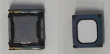 |
50mW 30Ω 9*8*2mm AAC WT | 1 | PCS |
| 3 | Motherboard | 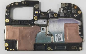 |
/ | 1 | PCS |
| 4 | Front camera | 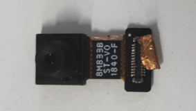 |
GC8034W 8M 6.6*6.6*4.9mm 1/4'' BTB connect ST-8M833B WT | 1 | PCS |
| 5 | Rear camera | 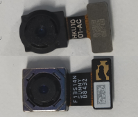 |
13M+2M | 1 | PCS |
| 6 | Middle frame | 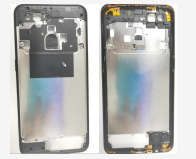 |
/ | 1 | PCS |
| 7 | Fingerprints sensor assembly | 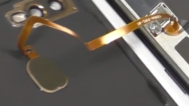 |
ET520JG 12.6*9.8*1.4mm BTB FS22124BIR E338 coating Gold ring WT | 1 | PCS |
| 8 | SIM bracket | 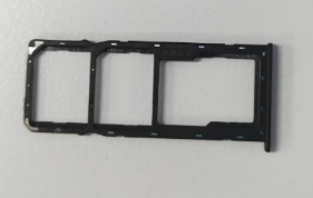 |
/ | 1 | PCS |
| 9 | Camera lens | 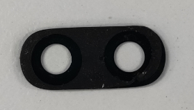 |
18511 black; glass | 1 | PCS |
| 10 | Press steel sheet for Fingerprint BTB | 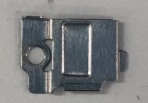 |
18511 stainless steel WT | 1 | PCS |
| 11 | Screws | 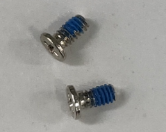 |
Round M1.4×H3.0×D2.5 head diameter 2.5 WT | 19 | PCS |
| 12 | Battery cover | 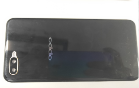 |
18511 with cushion without fingerprint hole WT | 1 | PCS |
| 13 | Battery | 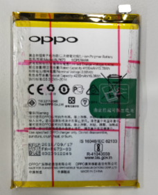 |
@4100/3.85V/0.7C BLP673 416587 FA I724 | 1 | PCS |
| 14 | RF cable | 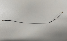 |
50Ω 170.3mm 818013838 WT | 1 | PCS |
| 15 |
Speaker
|
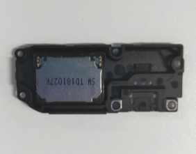 |
1W 8Ω 17×12×2.35mm XW WT | 1 | PCS |
| 16 | Antenna board | 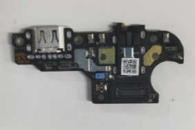 |
/ | 1 | PCS |
| 17 | Motor | 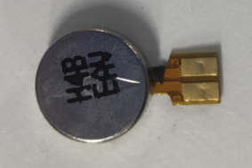 |
8mm×3.0mm 3V 31±15% HZF WT | 1 | PCS |
| 18 | USB FPC | 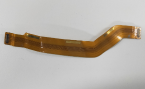 |
98607_3_11(U board)-M11-patch 18513 WT | 1 | PCS |
| 19 | Power key FPC | 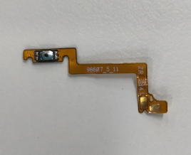 |
98607_4_11(V board)-M11-patch 18513 WT | 1 | PCS |
| 20 | Volume key FPC | 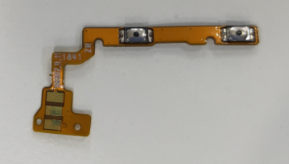 |
98607_5_11(P board)-M11-patch 18513 WT | 1 | PCS |
5. Disassembly steps
| NO | Steps | Figure |
Cautions
|
|---|---|---|---|
| 1 | Remove sim card holder | 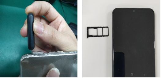 |
/ |
| 2 | Remove battery cover | 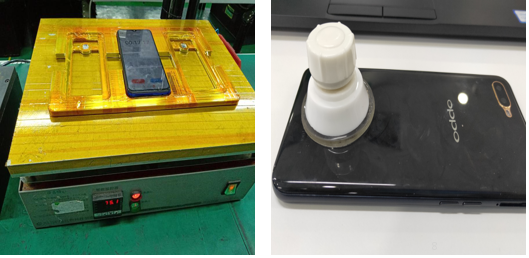 |
Time:2-4min Temperature:75℃ |
| 3 | Remove fingerprint steel sheet | 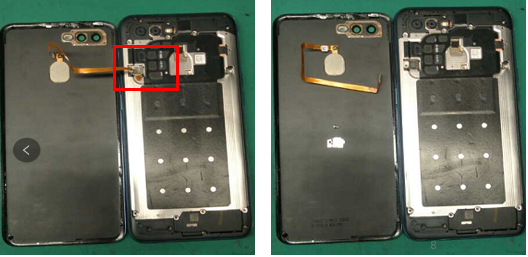 |
Be careful not to rip the FPC |
| 4 | Remove the middle frame | 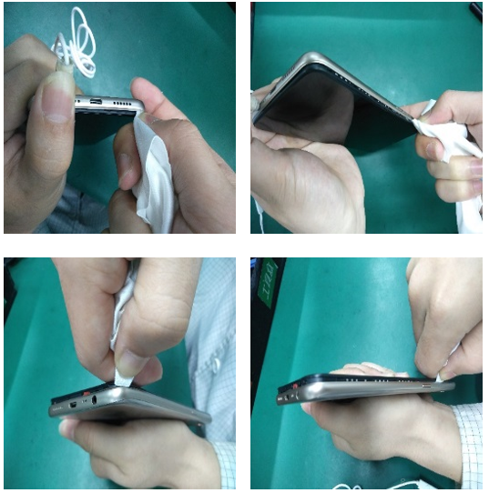 |
After disassembly, the battery cover and middle frame should be checked for appearance, whether there are cracks or color differences in the positions of buttons, headphone holes and card holder |
| 5 | Remove the battery | 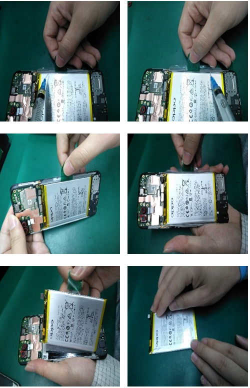 |
Note: the battery should be pulled straight as far as possible and avoid pulling the battery vertically to cause the battery to deform . Check for puncture, indentation, leakage and other defects after removing the battery |
| 6 |
Remove the mainboard and camera |
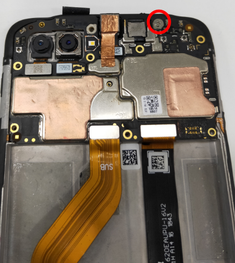 |
Be careful not to destroy the RF socket |
| 7 | Remove RF cable, speaker, USB-FPC and antenna board | 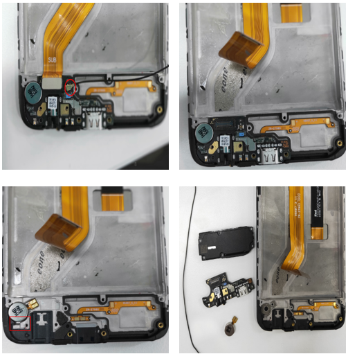 |
Be careful not to destroy the RF socket |
| 8 | Remove receiver and key FPC | 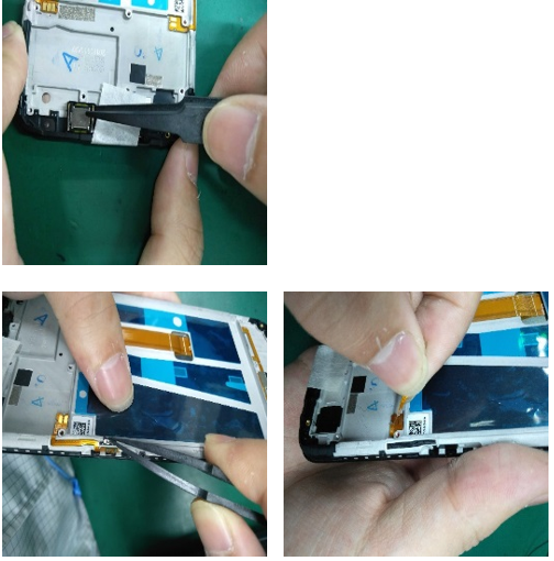 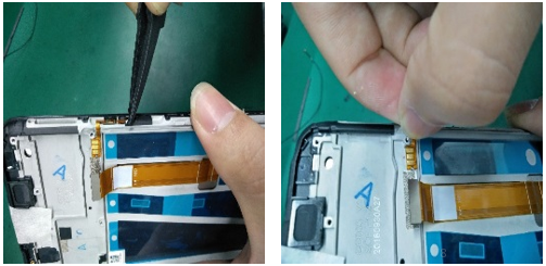 |
/ |
| 9 | Remove the fingerprint | 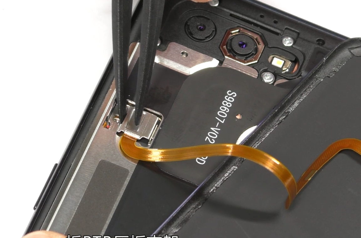 |
Temperature:75°C,Time:3min |
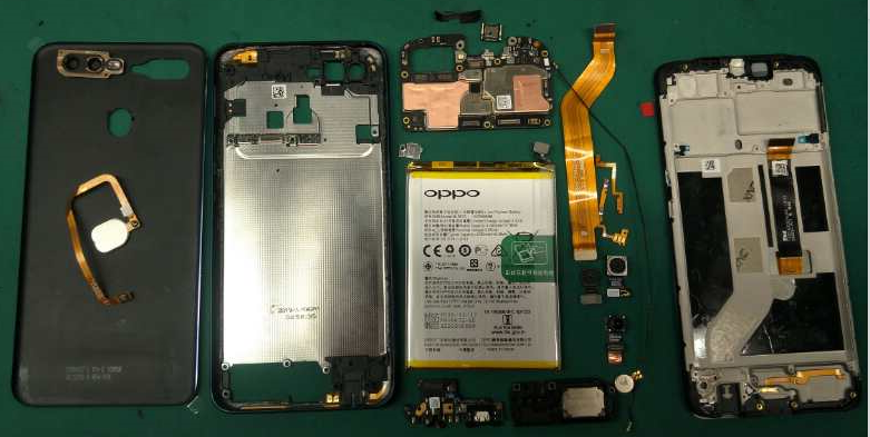
| All parts of the phone as shown |
 |
||
6. Assembly Step
| NO | Steps | figure | Cautions |
|---|---|---|---|
| 1 | Assemble key FPC | 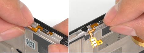 |
/ |
| 2 | Assemble the receiver and motor | 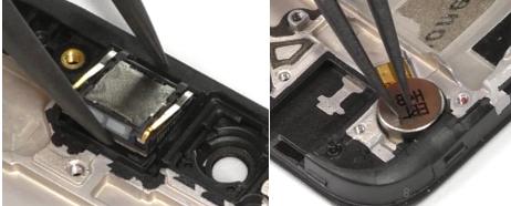 |
Pay attention to the direction of the receiver’s pin |
| 3 | Assemble the antenna board | 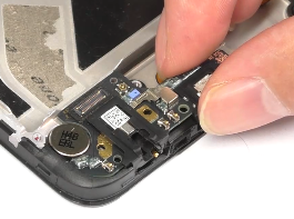 |
/ |
| 4 | Assemble the speaker | 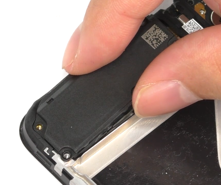 |
/ |
| 5 | Assemble the speaker set screw | 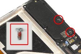 |
|
| 6 | Assemble the RF cable | 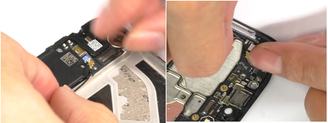 |
Pay attention to RF socket |
| 7 | Assemble the mainboard | 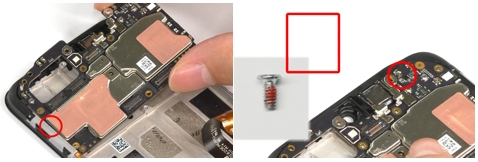 |
Put it from the left side , then screw in the right side |
| 8 | Assemble the main FPC | 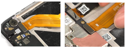 |
Need to smooth with your hands and do not wrinkle. |
| 9 | Assemble PET sheet | 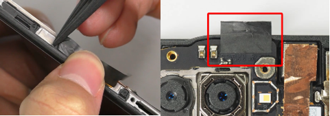 |
/ |
| 10 | Assemble the battery cushion foam | 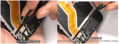 |
/ |
| 11 | Assemble the front camera | 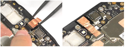 |
/ |
| 12 | Assemble the rear camera | 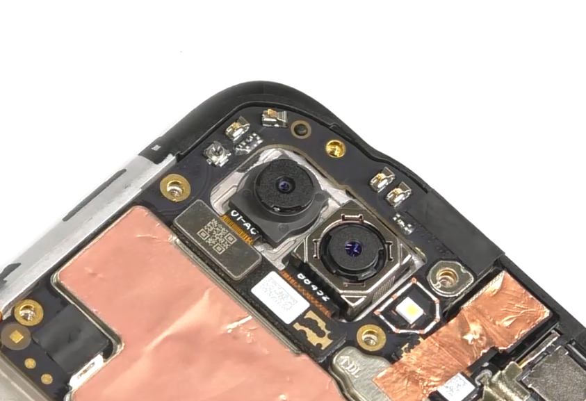 |
/ |
| 13 | Paste the battery tear paper | 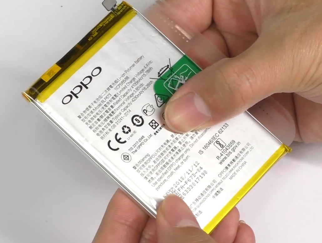 |
The tear paper must be replaced with a new one |
| 14 | Assemble the battery | 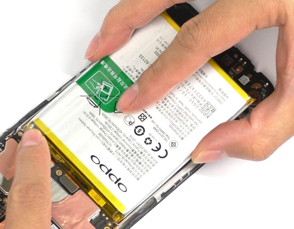 |
/ |
| 15 | Assemble the middle frame | 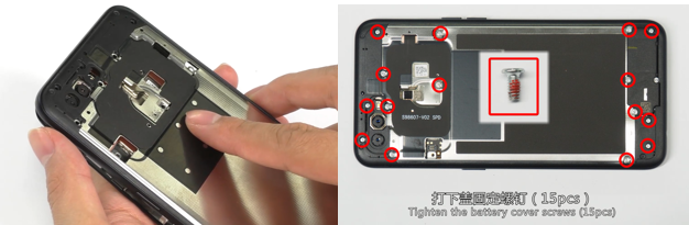 |
/ |
| 16 | Paste Double-sided adhesive tape for battery cover | 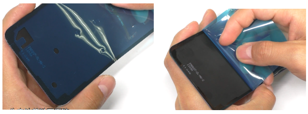 |
Not to touch the dust |
| 17 | Assemble the fingerprint module | 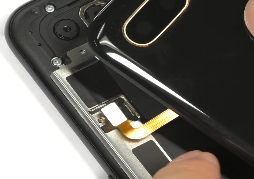 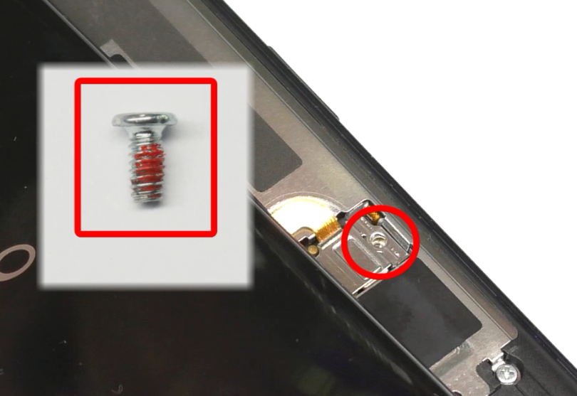 |
/ |
| 18 | Assemble the battery cover | 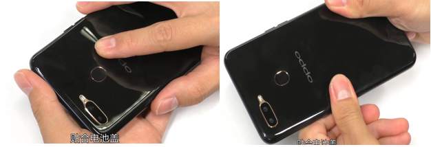 |
/ |
| 19 | Insert the card holder | 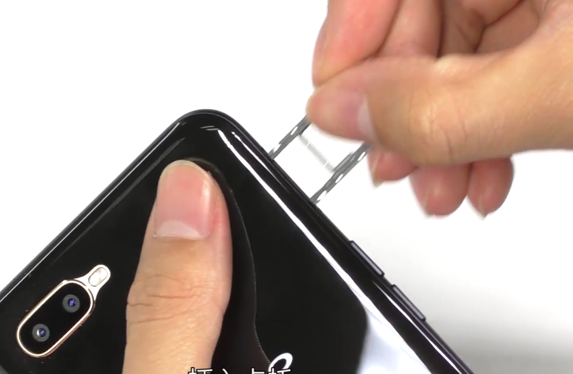 |
/ |
7. Calibration
After reassembling the phone, it is necessary for the technicians to enter in *#899# to finish the automatic test. Manually take the photo in the “After-sale Camera Calibration” (Please take a photo for the stereoscopic object or a portrait). If the item passes, it will enter the next item; if this item fails , please re-do the test. If it fails for multiple times, reassemble the camera and test again.
8. Function test
Enter the functional test:
*#899#>Automatic test
The "Confirm" dialog box will pop up after the test completes, if there is no problem choose “Pass”, otherwise choose “Fail”.
| NO | Testing item | Testing requirement |
| 1 | LCD test | Detect whether there are black spots, bright spots and other anomalies in each interface |
| 2 |
|
If the interface jumps to the next test, the test is passed |
| 3 | Vibration | 1.Get ear close to check whether there is noisy vibration 2.Check there is no vibration, or weak vibration |
| 4 | Front camera preview | 1. For the white interface of the camera, detect whether there are black spots, black lines or blurred screen. 2. For the black interface, check whether there are bright spots, white spots or blurred screen; |
| 5 | Rear camera preview | 1. For the white interface of the camera, detect whether there are black spots, black lines or blurred screen. 2. For the black interface, check whether there are bright spots, white spots or blurred screen; 3. For the interface with words, check whether the focus is clear |
| 6 | Second rear camera preview | 1. For the white interface of the camera, detect whether there are black spots, black lines or blurred screen. 2. For the black interface, check whether there are bright spots, white spots or blurred screen; 3. For the interface with words, check whether the focus is clear |
| 7 | After-sale camera calibration | Refer to "Rear camera calibration guide" |
| 8 | Flash-light test | Check the function and color of the flashlight |
| 9 | Echo test | Testing MIC: Blow the air to the MIC hole on the bottom of the phone. If the receiver (earphone) sounds, the test is passed |
| 10 | Charger | Use the OPPO adapter and USB cable to test. If the test is passed, it will automatically jump to the next test item. |
| 11 | Headset in-out plug test | Enter the earphone plug-in test with the OPPO earphone and the interface will automatically jump to the next test item. |
| 12 | Sensor self-test and calibration | When the phone enters into the Sensor self-calibration interface, the phone must be placed on the desk flatly. Then click the first calibration item. After the test is passed, it will automatically jump to the next test item |
| 13 | M-Sensor | Shake the phone from the left to the right side in the M Sensor in the test interface. After the test passes, it will automatically jump to the next test item |
| 14 | Proximity-sensor test | Use the palm to cover the light sensor hole in the Proximity sensor test interface, and the screen will turn green from black. If the test is passed and the interface jump to the next test, the sensor is without failure. |
| 15 | Key Test | Press the power key and volume key, After the test passes, it will automatically jump to the next test item; |
| 16 | Fingerprint auto test | It will automatically jump to the next test item |
| 17 | Media test | Click the 20-4K(-3db)signal” to test the sound in the audio& video test interface. The interface will enter the “Confirm” dialogue box after tested for 5 seconds Then judge the test result; |
| 18 | Call Test | If the phone has been installed with the operator's SIM card, dial the corresponding operator's phone number. If no card is inserted, call the 112 test (It is recommended to install the SIM card to call). Check according to requirements, press the return key to enter “Confirm” dialog box, and select the result of the judgment; |
9. Cautions
1. Sensory test items require staff to judge the results such as LCD test, vibration test, front camera test, rear camera test, flashlight test, echo test, audio test, and call test. Therefore, the results must be judged according to test requirements
2. After the test is passed, the interface will automatically jump to the "Confirm" dialog box. Only the "Confirm" button needs to be tested for the echo test and call test.
3. It is not allowed to press the return key while the test has not finished yet and judge the result in advance.
4. Materials that need to be replaced after disassembly:
| Materials that need to be replaced after disassembly | |
| 1 | Bottom cushion in the battery compartment |
| 2 |
|
| 3 | Easy-tore paper for battery |