R17 Pro Service Manual-V1
Views: 0 • Likes: 0

Confidential
Content
1. Guidance
2. General Repair Information
3. Product Overview
4. Exploded View of Phone’s Structure
5 .Disassembly Steps
6. Installation steps
7. Calibration
8. Post-maintenance functional test
9. Precautions
1. Guidance
1.1 Guidance Overview
The purpose of this document is to help OPPO level1 and level 2 maintenance engineers to carry out service to OPPO products. This Service Manual is to be used only by authorized OPPO maintenance service centers, and the content shall be keep in confidential. Please note that OPPO provides also other guidance documents (e.g. Technical Service Bulletins) for maintenance service cooperative corporations, therefore, please follow these regularly and comply with the given instructions. While every endeavor has been made to ensure the accuracy of this document, some errors may exist. If you find any error or if you can offer further suggestions, please notify OPPO by using the address below: zhouyangguang@oppo.com.
Please keep in mind also that this document is continuously being updated and modified, please keep watching out for the newest version.
1.2. Warnings and Cautions
Please refer to the phone's user guide for instructions relating to operation, service and maintenance including important safety information. Note the following:
Warnings
1. Service centers may be required to install the handset’s
vehicle-mounted system in vehicles. Under certain fault conditions, the handset's RF signals may affect the operation of the vehicles' electric power management systems and anti–skid braking systems (ABSs). If necessary, consult the dealer/manufacturer to determine the immunity of vehicle electronic systems to RF energy.
2. The handset must not be operated in areas likely to contain potentially explosive atmospheres, such as petrol stations, gas stations and blasting areas.
3. Operation of any radio transmitting equipment, including handsets, may interfere with the functionality of the medical devices protected by industrial mechanisms. Consult the manufacturer of the medical devices if necessary. Other electronic equipment may also be subject to interference.
2. General Repair Information
※In this section the technician will get some general hints to carry out repairs:
Customer service personnel can download and read product documentation on:Download and read the product guide or user manual on the site:ftp:// :ftp://wxfuwu@172. 16. 103. 212:919
Before starting the repair, you must enter the ESD Protected Area and connect your wristband. Use gloves to avoid corrosion and fingerprints. Protect windows and display screens with a film to avoid dust and scratches. When cleaning the metal pads, you have to use a soft cloth/ESD brush and isopropanol solution. It is not allowed to use an eraser because it scratches the surface and will lead later on to oxidation and corrosion. Mechanical parts (except shielding covers and bent parts), which cannot be repaired in the event of a failure, can only be replaced, if they are not soldered. After removing and maintaining the shielding covers, make sure to replace them with new ones. Otherwise, the high-frequency leakage can have an influence on the device. Always use original OPPO spare parts. Check the soldering joints of the parts, which are concerned regarding the indicated error (e.g. soldered connectors or switches) and re-solder them if necessary (only repair centers that can conduct lead-free soldering). Remove redundant soldering flux after soldering. Assemble the handset with the standard screw torque (see the Introduction of the Service Manual).
Always use your own equipment for testing where you are sure that it works. For complaints about charger function, please test the handset with your own charger to be sure if the handset or charger causes the malfunction. When doing the fault log entries, always note the fault code, which caused the malfunction. The accuracy of this code will be a great help to quality improvement. Also, fill in the replaced part, if needed.
Many service documents are available on the FTP server: ftp://wxfuwu@172. 16. 103. 212:919, which will be notified via email. Please note that the documents shall be updated in time.
3. Product Overview
3.1. Product Introduction
| Parameter | Specification | |
| Screen | Screen | 19.5:9 FHD+ AMOLED` |
| Operating System | Operating System | Android 8.1 + ROM 5.2 |
| CPU | CPU | SDM710 8 Core Highest 2.2GHz |
| Memory | RAM | 6G/8G LPDDR4X |
| ROM | 128G UFS | |
| Camera | Front | IMX576 FF (25M) |
| Rear | IMX362 AF(12M+ Iris diaphragm 1.5/2.4F+7P Lens +OIS)+2T 7sx AF(20M)+TOF | |
| Network | Network Edition | 4G |
| Network Model | All net new 4 model | |
| Network Type | TD-LTE,FDD LTE,WCDMA、GSM | |
| Support Band | GSM: 850/900/1800/1900MHz WCDMA: Bands 1/2/4/5/6/8/19 FDD-LTE: Bands 1/2/3/4/5/7/8/12/17/18/19/20/25/26/28/32 TD-LTE: Bands 34/38/39/40/41 |
|
| Battery | Capacity | 1800mAh*2/1850mAh*2(MIN/TYP) |
| Data | Bluetooth | BT5.0 |
| WIFI | 2.4G:802.11b/g/n 5.1/5.8G: 802.11a/g/n/ac |
|
| Sensor | L-sensor,G-sensor,Distance-sensor, 、E-compass,Visual Gyro Sensor | |
| SIM Card | Double Nano card (note the distinction between single card countries) | |
| T card External Memory | N/A | |
| Earphone | Type C headset | |
| Adapter | 10V/5A Super VOOC | |
| USB | Type C USB_3.1(Overseas does not do DP, it is different from domestic sales) | |
| Other Features | Dual flash, Fingerprint Unlock | |
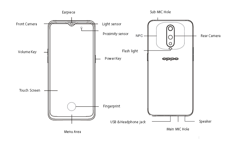
3.2.Product Appearance
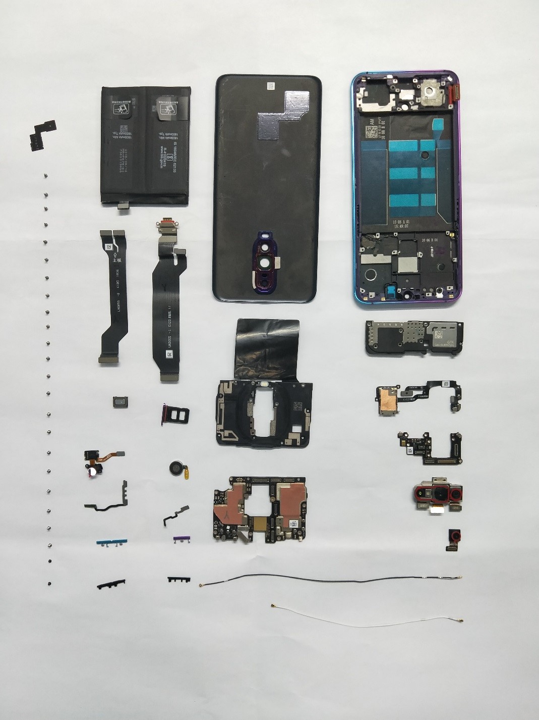
4. Exploded View of Phone’s Structure
4.1. Machine decomposition diagram
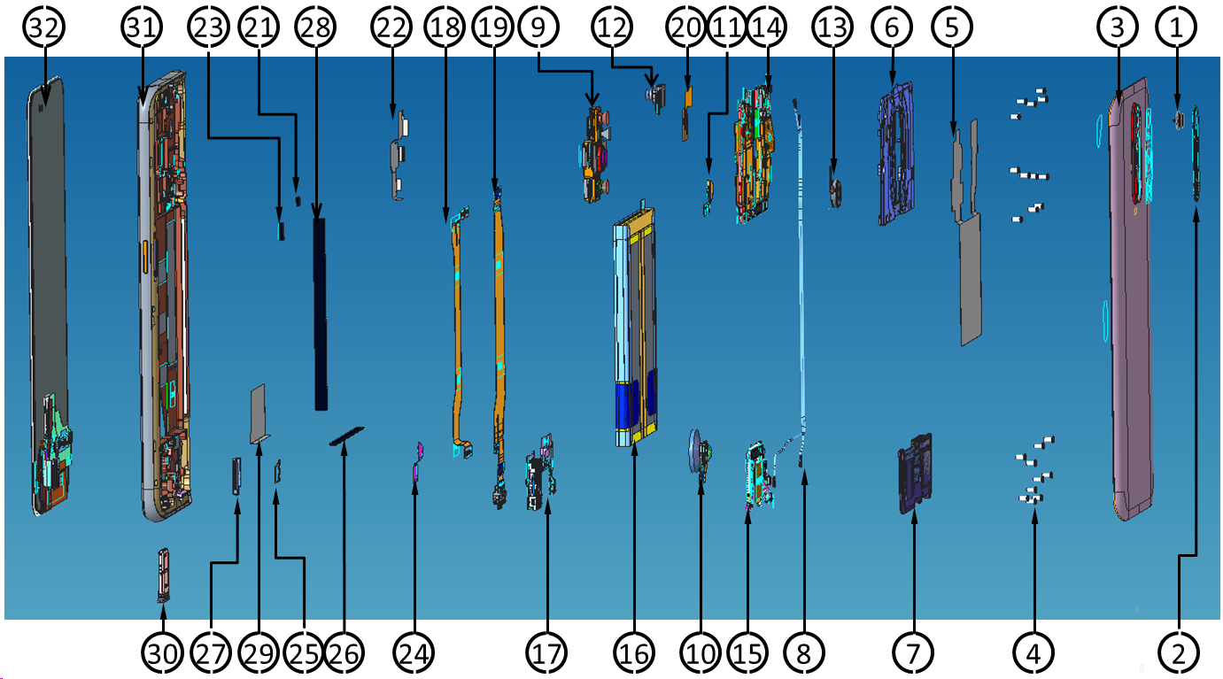
| Serial number | Material coding | Material name |
| 1 | 4720808 | TOF camera lens (Rear) |
| 2 | 4720805 | Camera lens (Rear) |
| 3 | 4720902 | Battery Cover |
| 4 | 4210648 | Machine tapping screw |
| 4210654 | Machine tapping screw | |
| 5 | 4874719 | FMI Shielding cover graphite sheet |
| 6 | 3882305 | Motherboard press plate bracket |
| 7 | 8511066 | Speaker |
| 8 | 2180585 | RF Cable |
| 2180586 | RF Cable | |
| 9 | 9490665 | Dual Camera |
| 10 | 9180302 | Fingerprint sensor module |
| 11 | 4962426 | Flash light |
| 12 | 9490650 | Camera |
| 13 | 8710130 | Vibration motor |
| 14 | 4962791 | Motherboard |
| 15 | 4962488 | Antenna Board |
| 16 | 9560874 | Battery |
| 17 | 4962424 | S Board |
| 18 | 4962380 | L Board |
| 19 | 4962383 | USB FPC |
| 20 | 4874704 | Front camera copper foil |
| 21 | 4874700 | Volume Key waterproof foam |
| 22 | 4874702 | Camera conductive cloth (Rear) |
| 23 | 4874701 | Power key waterproof foam |
| 24 | 4874705 | Hidden fingerprint PET film |
| 25 | 4874706 | Hidden fingerprint double-sided tape |
| 26 | 4874698 | Battery support cushion |
| 27 | 4874703 | LCM through hole silicone plug |
| 28 | 4874699 | Battery compartment RF cable mat |
| 29 | 4875362 | LCM-PET sheet (large) |
| 30 | 3882187 | SIM card holder |
| 31 | 5469095 | Middle Frame assembly |
| 32 | 9400987 | OLED Display |
4.3 Material Picture Table
| No. | Material Code | Material Name | Physical Picture |
|---|---|---|---|
| 1 | 4902006/4902011(Radiant Mist) 4902005/4902010(Condensed green) |
Upper Screen Cover Assembly | 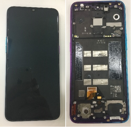 |
| 2 | 4901958/4902004 (Radiant Mist) 4901957/4902003 (Condensed green) |
Battery Cover Assembly | 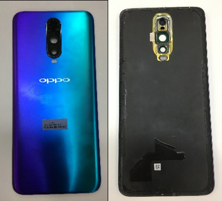 |
| 3 | 4902007(8+128G) 4902008(6+128G) |
Motherboard Assembly | 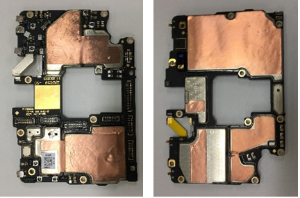 |
| 4 | 4902013 | Fingerprint assembly | 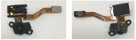 |
| 5 | 4902012 | Battery Assembly | 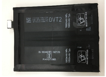 |
| 6 | 4962868 | FPC patch semi-finished product (USB FPC) |
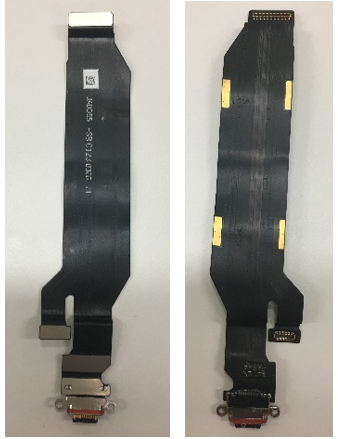 |
| 7 | 4962380 | FPC patch semi-finished product (LAD055- FPC) |
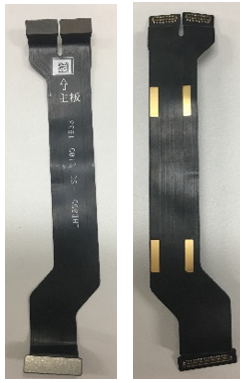 |
| 8 | 4962872 | FPC semi-finished product (SAD055-FPC) |
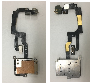 |
| 9 | 8511088 | Speaker | 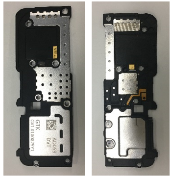 |
| 10 | 9490650 | Camera (Front) |
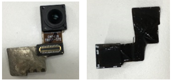 |
| 11 | 8520156 | Receiver | 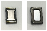 |
| 12 | 9490665 | Camera (Rear) |
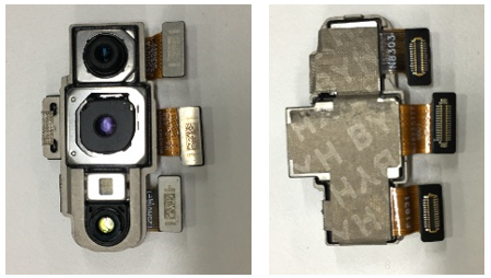 |
| 13 | 2180585(White) 2180586(Black) |
RF Connection Cable | 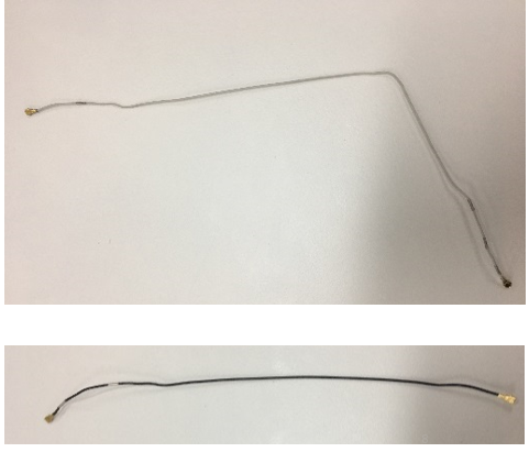 |
| 14 | 4902009 | Motherboard Bracket | 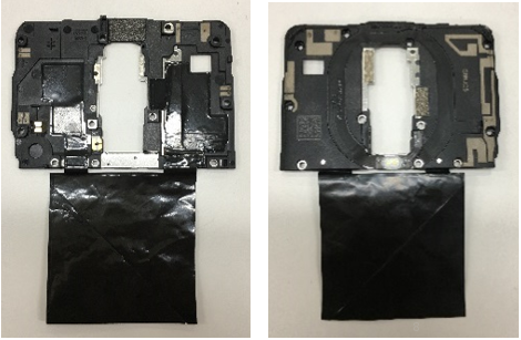 |
| 15 | 3882458(Radiant Mist) 3882187(Condensed green) |
SIM Card Holder | 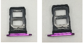 |
| 16 | 8710130 | Vibration Motor | 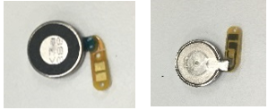 |
| 17 | 4962428 | PCB Semi-finished product | 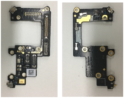 |
Note: This table is used only for the name of the annotation. It is not suitable for the preparation of materials. Please refer to the “Price list of Commonly-used Materials and Accessories” for the preparation.
5 .Disassembly Steps
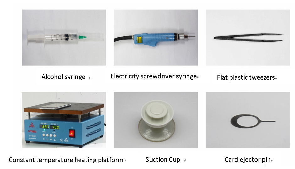
5.1 Disassembly Tool
The tools required for disassembly are shown in the figure below, including electrostatic wristband (electrostatic gloves), electric batch (crosshead), constant temperature platform, 2.5ml alcohol syringe (blue plastic head), flat plastic tweezers, low-viscosity protective film, Dust-free cloth, thimble/ejector pin, disassembling rod, disassembling sheet, etc.
5.2 Preparation
(1)Must be power-off before disassembling, the system power-off method is long press the power key to slide off
(2)The forced power-off method is to use the engineering command *#911# or press and hold the volume + button and the power key for about 8 seconds until the display goes out.
5.3 Disassembly Steps
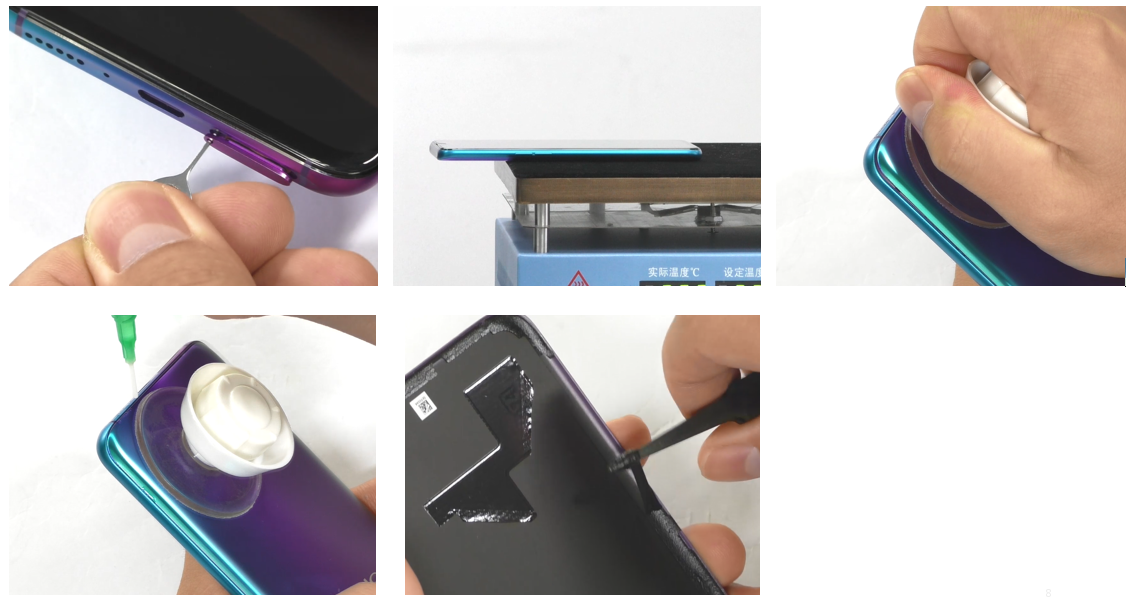
(1)Remove the card tray and remove the battery cover
1)Use the ejector pin to remove the card tray first;
2) Clean the battery cover with a piece of dust-free cloth, check the appearance of the battery cover and the middle frame, and do not leave any foreign matter in there. Then put it on a constant temperature platform and place it on the heating platform with the back side facing down. Be careful not to put the camera on the platform. Heating requirements: The temperature platform parameters require 70°C-80°C and for 5-10mins. Use the suction cup to remove the battery cover from the side of the power button. During the removal process, adjust the suction cup position according to the tightness. Note that when the battery cover and the middle frame are being separated, it is forbidden to pull out the battery cover vigorously from the upper cover;
3)After the battery cover is disassembled (there is still residual temperature), the double-sided tape at the inner edge of the battery cover should be removed. If the rubber there is difficult to remove, use the clean cloth with alcohol to clean it.
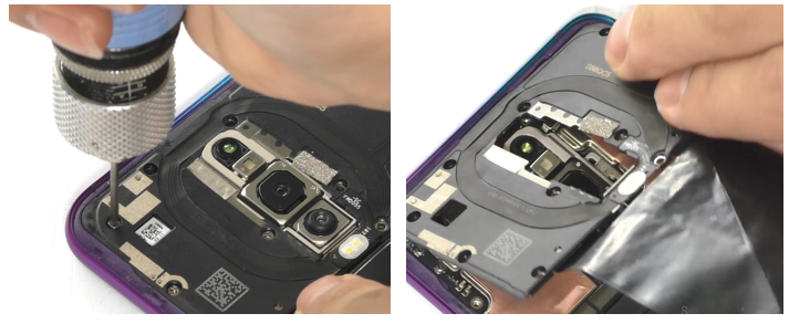
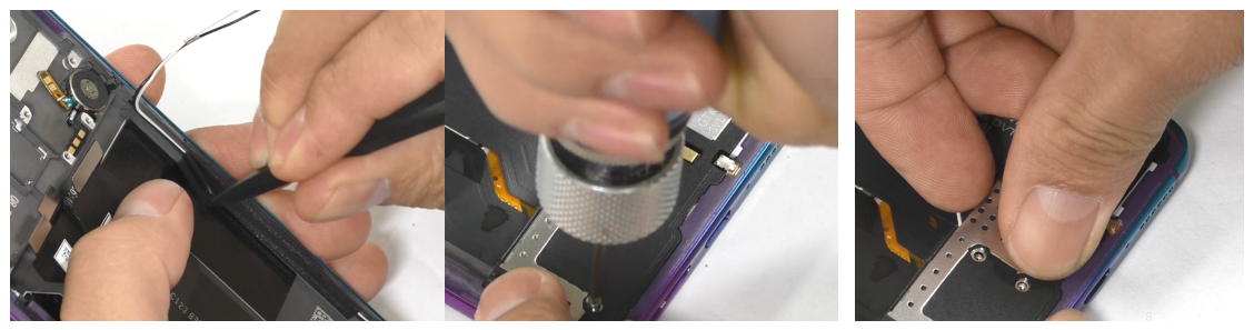
5.4 Disassemble screws, motherboard bracket
1) Use the Cross electric screwdriver to remove the mother board bracket and the antenna board bracket screws for a total of 19pcs. The electric screwdriver should be connected vertically with the screws, and should not be deviated;
2) Then remove the motherboard bracket, pay attention to disassemble from the lower right corner of the motherboard bracket to prevent the bracket from deformation.
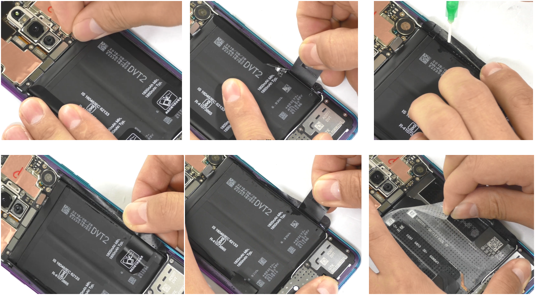
5.5 Disassemble the battery
1) Use a plastic tweezers to open the battery BTB buckle from the top of the battery BTB with tweezers (or nails), and then pull the easy-torn handle (torn handle in two sides) to open the easy tearing paper edge on the battery tear side;
2) Use a small syringe of 2.5ml to inject about 0.2ML of alcohol into each of the two sides. Stand the phone 2-5S to make the alcohol fully penetrate under the stickers on both sides. After standing still, pull the handle (you need to gently pull it on both sides) to slowly pull up the battery (note, pull the battery straight as far as possible to avoid pulling the battery vertically, causing the battery to deform). Take care to avoid wrinkles in the battery wrap and make a service mark in the corresponding position of the battery. Then remove the easy-tore paper from the mobile phone, pay attention to avoid the wrinkles of the battery wrapper, and make the maintenance mark in the corresponding position of the battery. Immediately attach the battery double-sided adhesive release paper after removing the battery. Then use plastic tweezers (or nails) to remove the foam and RF cable foam at the bottom of the battery compartment.
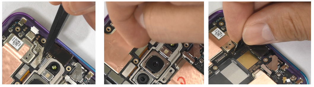
5.6 Remove the front and rear cameras
Use plastic tweezers to remove the front and rear conductive cloth, front and rear BTB buckle total 4PCS, then remove the front and rear cameras and use the protective film to protect the front and rear camera.
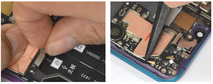
5.7 Remove the motherboard BTB buckle, RF cable and the motherboard
1) Use plastic tweezers (or nails) to remove the BTB buckle on the motherboard;
2) Use plastic tweezers (or nails) to remove the total RF cable from the motherboard (2PCS);
3) Remove the fixing screws of the mother board from the cross electric batch. The electric batch should be vertically connected with the screws, and the batch head should not be misaligned. Use fingers to remove the motherboard from the lower right corner of the motherboard.
5.8 Disassemble the speaker
1) Tear off the foam in the battery compartment with tweezers;
2) Remove the screws on the speaker with the electric batch, take the RF wire out of the wire slot, remove the speaker from the middle of the antenna board bracket, and then make the maintenance mark.
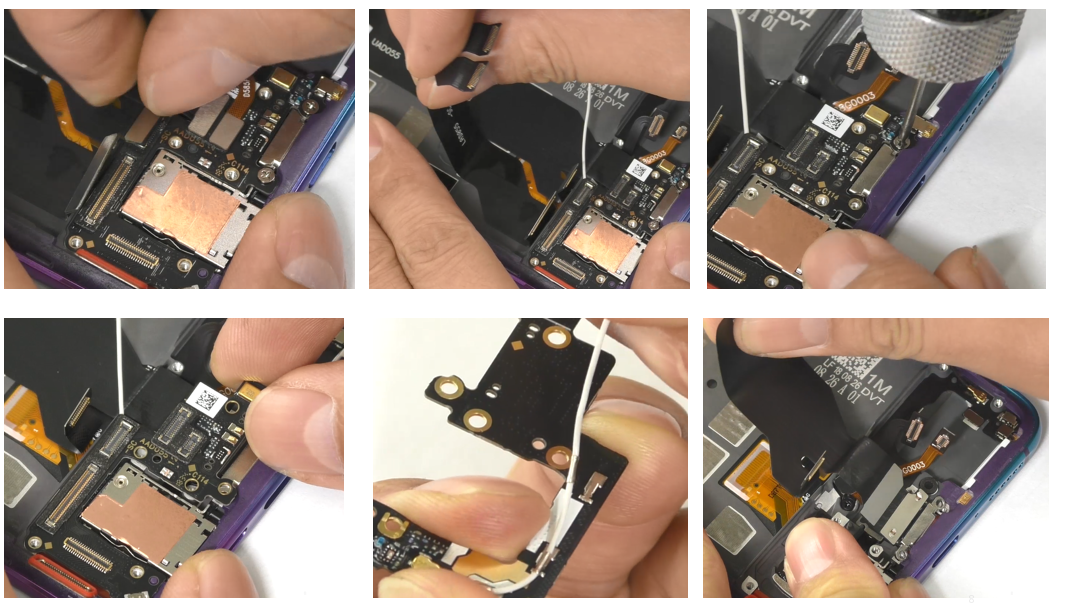
5.9 Remove L board, antenna board, U board
1) Loosen the BTB buckle on the antenna board for a total of 4 pcs, then remove the L board and use the original release paper to protect the double-sided tape on the L board;
2) Remove the fixing screws on the antenna board and remove the antenna board from the right side.
3) Remove the white RF cable from the antenna board, taking care not to pull the RF wire hard.
4) Then remove the USB FPC.
5.10 Remove the Fingerprint module, remove the SIM card holder FPC, remove the black RF line
1) Use the cross electric batch to remove the fingerprint mold screws for a total of 2pcs, and the electric batch should be vertically aligned with the screws. Use a plastic tweezers (or nails) to remove the fingerprint film, and use a mask to protect the touch screen opening, and use a release film to protect the fingerprint camera.
2) Use the plastic tweezers to lift the A board FPC, use your fingers to pull the FPC to the SIM card slot, then use the ejector pin to lift the SIM card holder and remove the entire SIM card holder;
3) Remove the black RF cable.
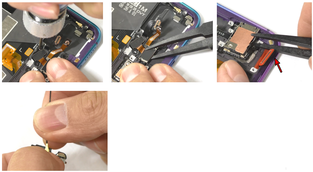
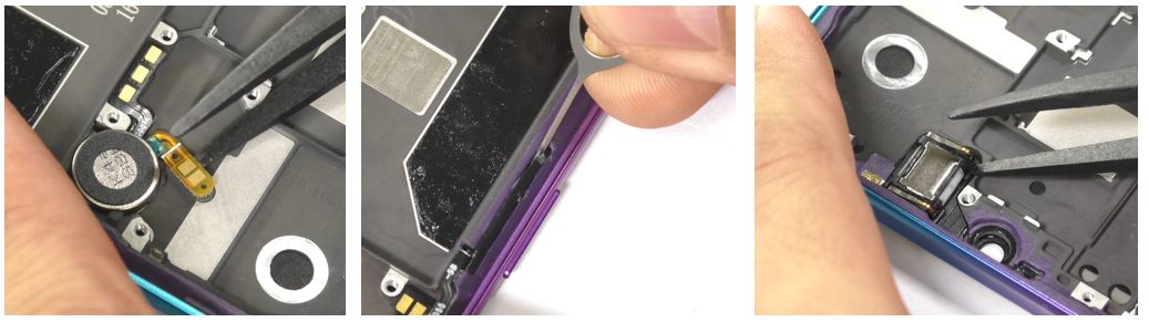
5.11 Remove the motor, remove the side buttons and side button FPC
1) Pick up the motor with a plastic tweezers, remove the motor, and remove the motor backing and residual double-sided tape in the motor compartment, and then put it into the original tray;
2) Use the stylus to lift it from the lower end of the side key bracket, then take out the button by hand, use the tweezers to lift the gold finger in the gold finger disassembly position (pay attention to the angle(prevent damage to the upper cover), take out the FPC, tear off the button waterproof padding;
3) Use the tweezers to remove the receiver.
Defective materials and all assembled parts of the whole machine:
Defective materials and all assembled parts of the whole machine:
Note:
(1) The stripe direction of the yellow stripe rubber head should follow the long side of the phone.
(2) After the calibration is completed, the phone needs to be restarted for the calibration to take effect;
8. Post-maintenance functional test
After the repair is completed, first tested and identified the fault for the user. After the identification is completed, the basic functions of the mobile phone must be tested, and it can be returned to the user after passing the test.
8.1Visual inspection:
Check whether the mobile phone display screen is dirty or not; the mobile phone has no gaps, cracked shells, cracked keys, scratches, and whether the USB has fallen off etc.
8.2 Functional test path:
1) Input *#899# in the dial interface > automatic test > function test;
2) Input *#807# in the dial interface> enter the function test.
8.3 Testing requirements
8.4. Test Method
1. LCD Test
Inputting *#807# in the dial interface will automatically enter the LCD test of the function test. Click on the screen to switch among red, green, blue, white, black, gray, gray scale , multicolor, and fruit colors, cables, highlights, black spots, etc.

After the test is finished, the interface will automatically appear the “Confirm” dialogue box. If the LCD test fails, select “FAIL”. If the LCD test is passed, select “PASS”;If the result is confirmed, the interface will jump to the next test.
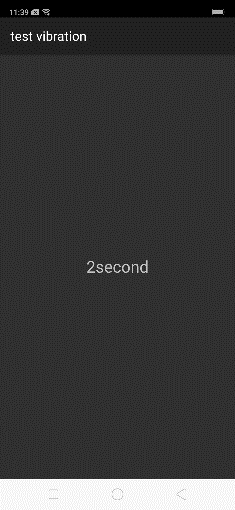
2. Vibration Test.
When the motor vibrates for 3 seconds, move the motor close to the ear. Test according to the above table. The “Confirm” dialog box will jump automatically after 3 seconds of the test. Select “PASS” if the test is passed. If there is noisy vibration, no vibration, or weak vibration, select "FAIL"
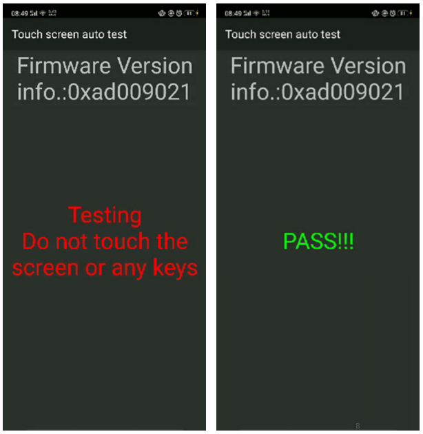
3 Touch Screen Automatic Test
The interface will jump to the touch screen automatic test after the last test was finished, and the mobile phone system will automatically test touch screen.
After the test is passed, it will automatically jump to the next test item; if the test fails, the interface will not jump. Press the return key to enter “Confirm” Dialog box, and select "FAIL";
Notice: Any replacement of screen or mainboard after sales must operate this step, or there will be abnormality: No function/Touch screen insensitivity/Disorderly touch point.
4. Front camera preview
After judging the result of the vibration, the Detection interface automatically entered for 5 seconds. Test according to the above test requirements. Judge the test result when the machine enters automatically “Confirm” dialog box after 5 seconds.
5. Rear camera preview
The Detection interface of main rear camera will be automatically entered for 5 seconds after judging the front camera. Test according to the above test requirements. Judge the test result when the machine enters automatically “Confirm” dialog box after 5 seconds.
6. Second rear camera preview
The Detection interface of sub rear camera will be automatically entered for 5 seconds after judging the main rear camera. Test according to the above test requirements. Judge the test result when the machine enters automatically “Confirm” dialog box after 5 seconds.
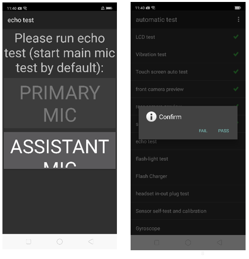
7. Echo test
In the echo test, if “Main MIC” is gray, the main MIC is being tested.;Blow the air to the MIC hole on the bottom of the phone. If the receiver (earphone) sounds, the test is passed; Then click on the " sub MIC" to test the sub MIC and blow air to the sub MIC hole on the top of the phone. If the speaker sounds, the test is passed. Press the return key to enter the “Confirm” dialog box and judge the result.
8. Flashlight test
The test interface of flashlight will be automatically entered for 5 seconds after judging the sub rear camera. Test according to the above test requirements. Judge the test result when the machine enters automatically “Confirm” dialog box after 5 seconds.
9. Flash Charger
Use the OPPO dedicated VOOC adapter and VOOC Line test. If the test is passed, it will automatically jump to the next test item. If the test fails, the interface will not jump. Press the return key to enter the “Confirm” dialog box and select "FAIL";
10. Headset in-out plug test
Enter the earphone plug-in test with the OPPO earphone and the interface will automatically jump to the next test item. If the test fails, the interface will not jump. Press the return key to enter the “Confirm” dialog box and select "FAIL";
11. Sensor self-test and calibration
When the phone enters into the Sensor self-calibration interface, the phone must be placed on the desk flatly. Then click the first calibration item. After the test is passed, it will automatically jump to the next test item; if the test fails, the interface will not jump. Press the return key to enter “Confirm” Dialog box, and select "FAIL";
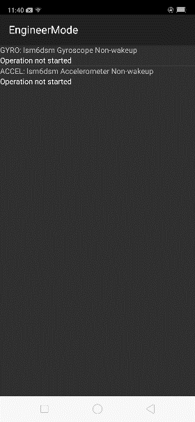
12. Gyroscope
After entering the test, take the mobile phone to draw the "8" word graphic.
13. M Sensor
Shake the phone from the left to the right side in the M Sensor in the test interface. After the test passes, it will automatically jump to the next test item; if the test fails, the interface will not jump. Press the return key to enter “Confirm” Dialog box, and select "FAIL"

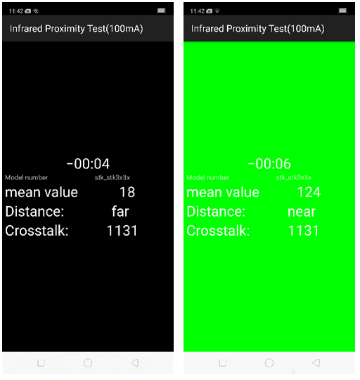
14 Infrared Proximity Test(100mA)
Use the palm to cover the light sensor hole in the Proximity sensor test interface, and the screen will turn green from black. If the test is passed and the interface jump to the next test, the sensor is without failure.
15 Infrared Proximity Test(150mA)
Use the palm to cover the light sensor hole in the Proximity sensor test interface, and the screen will turn green from black. If the test is passed and the interface jump to the next test, the sensor is without failure.
16 Key Test
Press the power Key, volume Key one by one. If the interface automatically jumps to the next test item without malfunction (If the key is stuck or rising, the Key is with failure).
17 Fingerprint auto test
Automatic test OK will display PASS, automatically jump to the next test item
18 Media Test
Check whether there is silence, weak sound, noisy sound, broken sound. If there isn’t failure with the speaker, it is passed.;
19 Call Test
If the phone has been installed with the operator's SIM card, dial the corresponding operator's phone number. If no card is inserted, call the 112 test (It is recommended to install the SIM card to call). Check according to requirements, press the return key to enter “Confirm” dialog box, and select the result of the judgment;
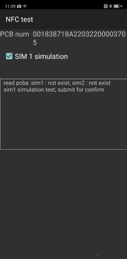
20 NFC Test
After the mobile phone automatically selects the SIM1 simulation, Put the rear camera area of the mobile phone to close the NFC card reader, if the card reader signal light changes from red to green, and is accompanied by a "drop" sound, which is a good product.( The tool does not arrive or does not order the tool area temporary alternative: After entering the test interface, increase the volume of the mobile phone, put the label containing the chip into the rear camera area of the mobile phone, and the mobile phone emits a "drop" sound as a good product)
21 TOF Test
Point the rear camera at the palm of your hand and see the palm outline. The TOF function is good and the camera interface will stay for 5 seconds.

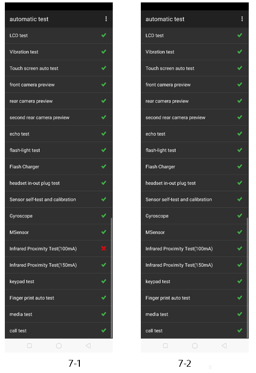
After the above 21 test items are tested, they will prompt to the test result interface. If the test PASS, project will hit “√”; if the test FAIL, project will hit “×”. Items showing "X" need to be clicked again to test, until it is displayed as shown below
9. Precautions
1. If the repair process involves replacing the motherboard or disassembling the screen assembly/fingerprint module, the phone must be recalibrated;
2. After the installation is completed, it must be calibrated and tested to ensure normal use after maintenance;
3. If the mobile phone needs filming in the service center, the phone must be recalibrated after replacement;
4. Sensory test items require staff to judge the results. For example, LCD test, vibration test, pre-test, post-test, flash test, echo test, audio test, and call test are all human judgment results. Therefore, the judgment result must be followed. Test requirements judgment;
5. It is forbidden to use the return key to judge the result in advance if the test item is not tested.
5 .Disassembly Steps
5.1 Disassembly Tool
The tools required for disassembly are shown in the figure below, including electrostatic wristband (electrostatic gloves), electric batch (crosshead), constant temperature platform, 2.5ml alcohol syringe (blue plastic head), flat plastic tweezers, low-viscosity protective film, Dust-free cloth, thimble/ejector pin, disassembling rod, disassembling sheet, etc.
5.2 Preparation
(1)Must be power-off before disassembling, the system power-off method is long press the power key to slide off
(2)The forced power-off method is to use the engineering command *#911# or press and hold the volume + button and the power key for about 8 seconds until the display goes out.
5.3 Disassembly Steps
(1)Remove the card tray and remove the battery cover
1)Use the ejector pin to remove the card tray first;
2) Clean the battery cover with a piece of dust-free cloth, check the appearance of the battery cover and the middle frame, and do not leave any foreign matter in there. Then put it on a constant temperature platform and place it on the heating platform with the back side facing down. Be careful not to put the camera on the platform. Heating requirements: The temperature platform parameters require 70°C-80°C and for 5-10mins. Use the suction cup to remove the battery cover from the side of the power button. During the removal process, adjust the suction cup position according to the tightness. Note that when the battery cover and the middle frame are being separated, it is forbidden to pull out the battery cover vigorously from the upper cover;
3)After the battery cover is disassembled (there is still residual temperature), the double-sided tape at the inner edge of the battery cover should be removed. If the rubber there is difficult to remove, use the clean cloth with alcohol to clean it.
5.4 Disassemble screws, motherboard bracket
1) Use the Cross electric screwdriver to remove the mother board bracket and the antenna board bracket screws for a total of 19pcs. The electric screwdriver should be connected vertically with the screws, and should not be deviated;
2) Then remove the motherboard bracket, pay attention to disassemble from the lower right corner of the motherboard bracket to prevent the bracket from deformation.
5.5 Disassemble the battery
1) Use a plastic tweezers to open the battery BTB buckle from the top of the battery BTB with tweezers (or nails), and then pull the easy-torn handle (torn handle in two sides) to open the easy tearing paper edge on the battery tear side;
2) Use a small syringe of 2.5ml to inject about 0.2ML of alcohol into each of the two sides. Stand the phone 2-5S to make the alcohol fully penetrate under the stickers on both sides. After standing still, pull the handle (you need to gently pull it on both sides) to slowly pull up the battery (note, pull the battery straight as far as possible to avoid pulling the battery vertically, causing the battery to deform). Take care to avoid wrinkles in the battery wrap and make a service mark in the corresponding position of the battery. Then remove the easy-tore paper from the mobile phone, pay attention to avoid the wrinkles of the battery wrapper, and make the maintenance mark in the corresponding position of the battery. Immediately attach the battery double-sided adhesive release paper after removing the battery. Then use plastic tweezers (or nails) to remove the foam and RF cable foam at the bottom of the battery compartment.
5.6 Remove the front and rear cameras
Use plastic tweezers to remove the front and rear conductive cloth, front and rear BTB buckle total 4PCS, then remove the front and rear cameras and use the protective film to protect the front and rear camera.
5.7 Remove the motherboard BTB buckle, RF cable and the motherboard
1) Use plastic tweezers (or nails) to remove the BTB buckle on the motherboard;
2) Use plastic tweezers (or nails) to remove the total RF cable from the motherboard (2PCS);
3) Remove the fixing screws of the mother board from the cross electric batch. The electric batch should be vertically connected with the screws, and the batch head should not be misaligned. Use fingers to remove the motherboard from the lower right corner of the motherboard.
5.8 Disassemble the speaker
1) Tear off the foam in the battery compartment with tweezers;
2) Remove the screws on the speaker with the electric batch, take the RF wire out of the wire slot, remove the speaker from the middle of the antenna board bracket, and then make the maintenance mark.
5.9 Remove L board, antenna board, U board
1) Loosen the BTB buckle on the antenna board for a total of 4 pcs, then remove the L board and use the original release paper to protect the double-sided tape on the L board;
2) Remove the fixing screws on the antenna board and remove the antenna board from the right side.
3) Remove the white RF cable from the antenna board, taking care not to pull the RF wire hard.
4) Then remove the USB FPC.
5.10 Remove the Fingerprint module, remove the SIM card holder FPC, remove the black RF line
1) Use the cross electric batch to remove the fingerprint mold screws for a total of 2pcs, and the electric batch should be vertically aligned with the screws. Use a plastic tweezers (or nails) to remove the fingerprint film, and use a mask to protect the touch screen opening, and use a release film to protect the fingerprint camera.
2) Use the plastic tweezers to lift the A board FPC, use your fingers to pull the FPC to the SIM card slot, then use the ejector pin to lift the SIM card holder and remove the entire SIM card holder;
3) Remove the black RF cable.
5.11 Remove the motor, remove the side buttons and side button FPC
1) Pick up the motor with a plastic tweezers, remove the motor, and remove the motor backing and residual double-sided tape in the motor compartment, and then put it into the original tray;
2) Use the stylus to lift it from the lower end of the side key bracket, then take out the button by hand, use the tweezers to lift the gold finger in the gold finger disassembly position (pay attention to the angle(prevent damage to the upper cover), take out the FPC, tear off the button waterproof padding;
3) Use the tweezers to remove the receiver.
Defective materials and all assembled parts of the whole machine:
Defective materials and all assembled parts of the whole machine:
| Materials that do not need to be scrapped | |||
| Middle frame assembly | OLED display | USB FPC | L board |
| Front camera | Rear camera | Receiver | Vibration motor |
| Motherboard bracket | SIM card tray | RF cable | Hidden fingerprint |
| Fingerprint sensor module | Lithium charge | Battery cover | S board |
| Speaker | Motherboard | SIM card holder | |
Note: Light-sensitive silicone sleeve, USB silicone sleeve, receiver decorative sheet, etc., must be scrapped and not reusable once disassembled;
General precautions:
(1) All accessories, including double-sided tape, graphite sheet, copper foil, conductive cloth, foam, cannot be reused once disassembled;
(2) All appearance parts must be inspected for appearance after being removed, and can be used only after confirming;
(3) All the function of components must be tested before normal use;
(4) Demolition parts shall be marked according to the general specifications, and the defective products shall be distinguished by marks to avoid mixing
6. Installation steps
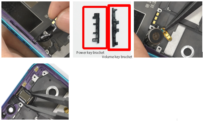
6.1 Install power button, receiver and motor
(1) Put the power key FPC into middle frame, use the tweezers to press the FPC into the corresponding position of the middle frame, use the power key to load the compression power button FPC, and then insert the power button bracket to fix the keys (Pay attention to the holder when installing the power button bracket.) The buckle is facing the bottom of the mobile phone. After inserting the bracket, press it tightly to ensure that the bracket does not lift. Press the power button FPC on the double-sided tape of the middle frame according to the position of the positioning post. Press the tweezers to ensure closeness and compaction; the way to install the volume key should be installed as above;
(2) Tear off the release paper on the motor, align it into the motor slot, and press the motor FPC with the tweezers to prevent lifting;
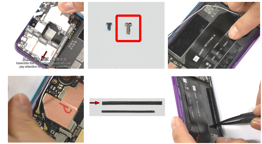
(3)Load the receiver body into the receiver slot from the left side, make sure the body is completely loaded into the slot without lifting.
6.2 Install SIM card FPC
Insert the SIM card holder from the top obliquely, fix the position, then install the SIM card holder FPC to the corresponding position, smooth the FPC.
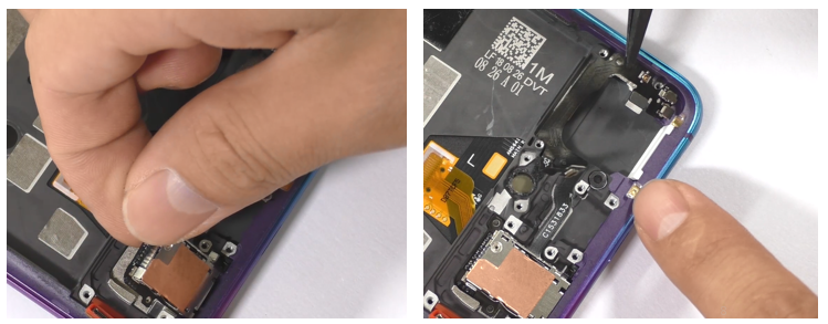
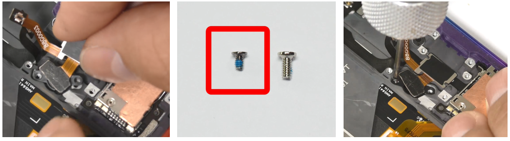
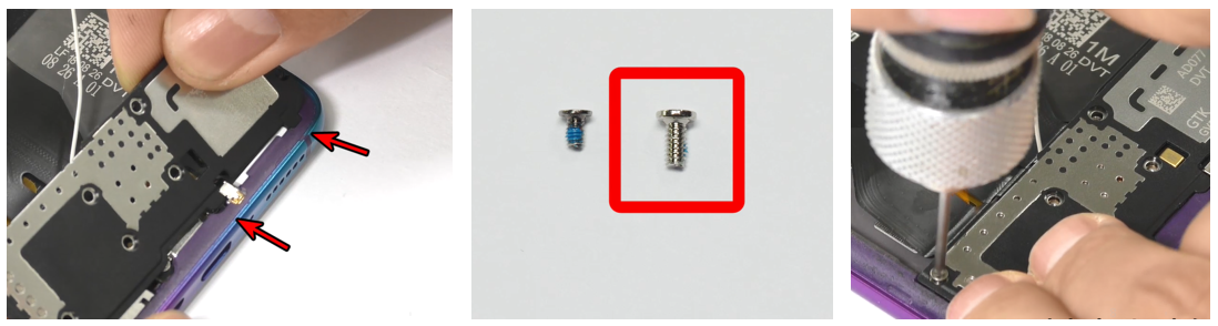
6.3 Install fingerprint module, USB FPC and antenna board
(1) Place the fingerprint module in the fingerprint slot, press it slightly so that it fits snugly in the slot, and use a screwdriver to fix the fingerprint module screw (note that the fingerprint module screw is 2 black screws);
(2) Install the USB FPC, insert the USB FPC from above, and ensure that it is inserted into the screw hole;
(3) Install the white RF cable on the antenna board, then insert the antenna board from above, gently press it to be flat, then fasten the BTB buckle on the antenna board and then install the antenna board screws.
6.4 Install Speaker
Install the speaker, load the speaker from the bottom of the phone, pay attention to the speaker to be buckled, after inserting, press the finger to confirm that the speaker is completely installed in the slot, and then put on the speaker screw.
6.5 Install motherboard, FPC and RF cable
(1) Tilt the board from the right side to the left and down, pay attention to the motherboard buckle and the edge, and do not force assembly. Insert the right side of the motherboard and press the motherboard so that it does not tilt and then snap the motherboard screws;
(2) Fasten the BTB buckle on the motherboard end, confirming that it is fully fitted after the complete fastening to prevent the FPC from undulating in the battery compartment;
(3) After the two black and white RF cables on the motherboard end are snapped into the RF holder, use the tweezers or fingers to insert the RF cable into the slot and straighten it;
(4) Flatten the foam (thin) on the side of the battery compartment and the foam (thick one) on the bottom of the battery compartment to ensure that the edges are flat and free of wrinkles.
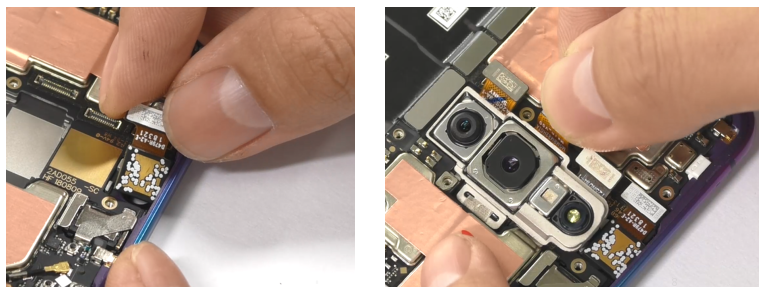
6.6 Install Camera
(1) Load the front camera and press the BTB buckle vertically after the camera is placed well;
(2) Load the rear camera module obliquely(pay attention to the shrapnel);Use fingers to press the edge of the module to confirm the flatness and buckle the BTB buckle; attach the graphite film to the front camera and smooth it to avoid lifting and wrinkles.
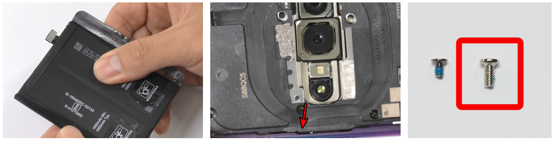
6.7 Install Battery, BTB press plate and battery cover
(1) Replace the battery with a new easy-tore sticker to ensure that the easy-tore sticker fits and is flat. After checking the bottom of the battery compartment without foreign matter, snap the battery BTB buckle , then put the battery into the battery compartment and press it gently by hand to make it fit after the battery is placed;
(2) Aligning the buckle, load the motherboard press plate obliquely, and use a screwdriver to snap the screw;
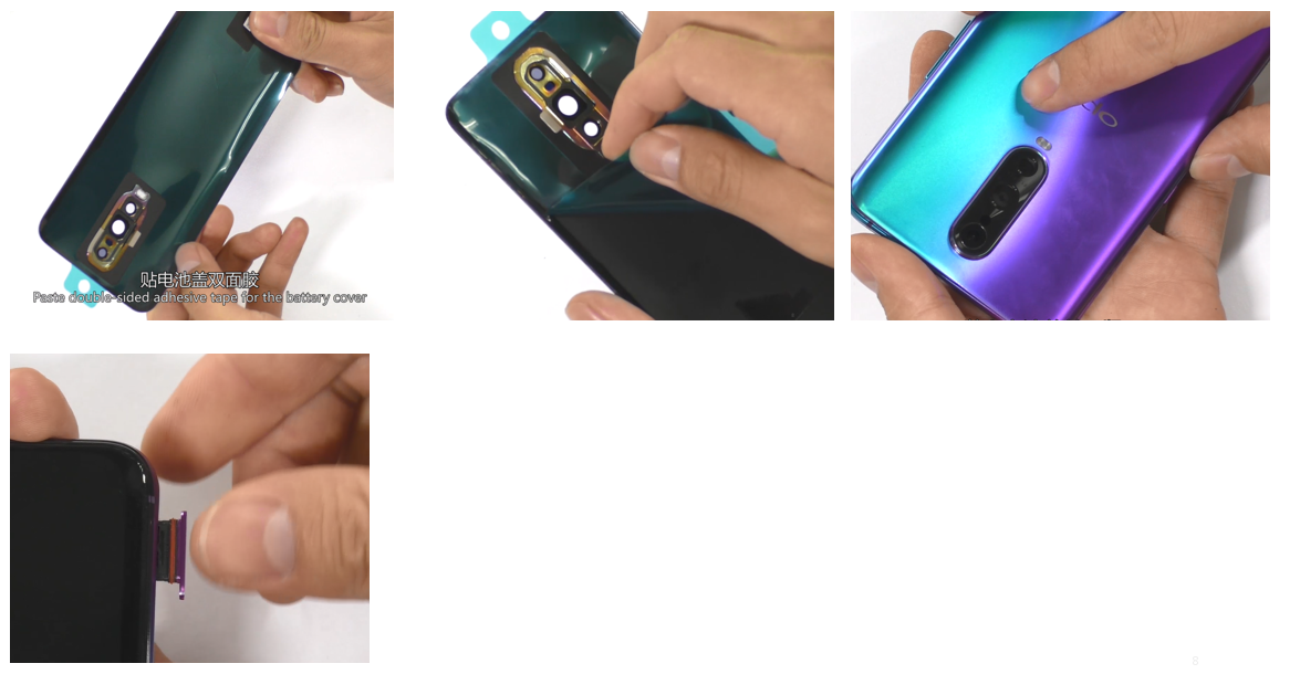
(3) After confirming that the graphite sheet is flat, attach the battery cover double-sided adhesive on the inside of the battery cover, and the notched position should be toward the bottom of the battery cover. Press the release paper to make the double-sided adhesive tightly. The double-sided adhesive should not exceed the outside of the battery cover without wrinkles;
(4) Remove the release paper on the double-sided tape of the battery cover, align the battery cover with the edge of the phone, press the battery cover and the phone, and then insert the SIM card holder.
The whole machine is assembled and enters the calibration process.。
7. Calibration
If the upper display assembly, the motherboard, fingerprint module, or protective film is replaced, the following fingerprint calibration must be operated.
Calibration path: input *#899# in the dial interface>Aftersales Devices Calibration> Enter password “6776” >Infrared Proximity Calibration > Fingerprint calibration,Specific operations refer to calibration page hints:
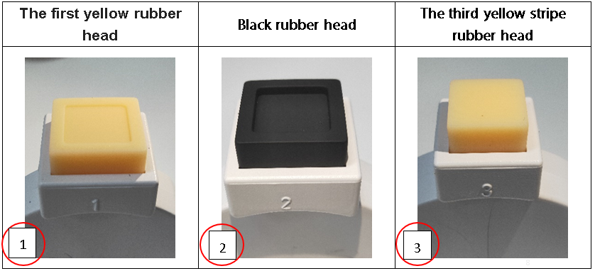
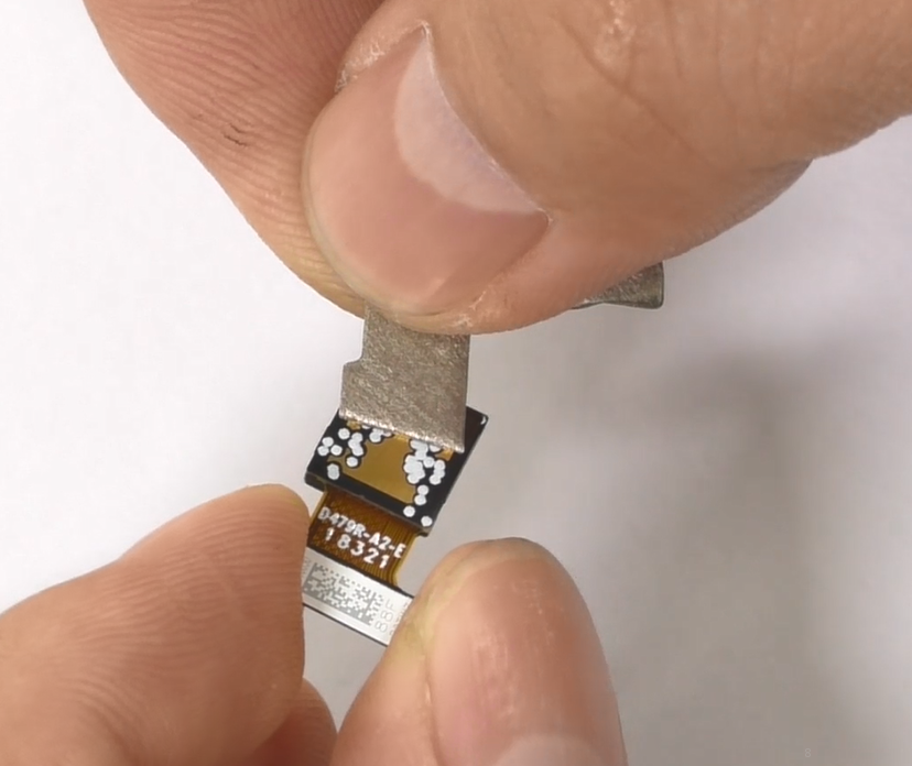
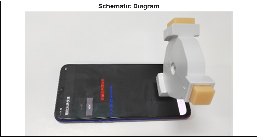
As shown on the right, the yellow stripe rubber head has parallel stripes
General precautions:
(1) All accessories, including double-sided tape, graphite sheet, copper foil, conductive cloth, foam, cannot be reused once disassembled;
(2) All appearance parts must be inspected for appearance after being removed, and can be used only after confirming;
(3) All the function of components must be tested before normal use;
(4) Demolition parts shall be marked according to the general specifications, and the defective products shall be distinguished by marks to avoid mixing
6. Installation steps
6.1 Install power button, receiver and motor
(1) Put the power key FPC into middle frame, use the tweezers to press the FPC into the corresponding position of the middle frame, use the power key to load the compression power button FPC, and then insert the power button bracket to fix the keys (Pay attention to the holder when installing the power button bracket.) The buckle is facing the bottom of the mobile phone. After inserting the bracket, press it tightly to ensure that the bracket does not lift. Press the power button FPC on the double-sided tape of the middle frame according to the position of the positioning post. Press the tweezers to ensure closeness and compaction; the way to install the volume key should be installed as above;
(2) Tear off the release paper on the motor, align it into the motor slot, and press the motor FPC with the tweezers to prevent lifting;
(3)Load the receiver body into the receiver slot from the left side, make sure the body is completely loaded into the slot without lifting.
6.2 Install SIM card FPC
Insert the SIM card holder from the top obliquely, fix the position, then install the SIM card holder FPC to the corresponding position, smooth the FPC.
6.3 Install fingerprint module, USB FPC and antenna board
(1) Place the fingerprint module in the fingerprint slot, press it slightly so that it fits snugly in the slot, and use a screwdriver to fix the fingerprint module screw (note that the fingerprint module screw is 2 black screws);
(2) Install the USB FPC, insert the USB FPC from above, and ensure that it is inserted into the screw hole;
(3) Install the white RF cable on the antenna board, then insert the antenna board from above, gently press it to be flat, then fasten the BTB buckle on the antenna board and then install the antenna board screws.
6.4 Install Speaker
Install the speaker, load the speaker from the bottom of the phone, pay attention to the speaker to be buckled, after inserting, press the finger to confirm that the speaker is completely installed in the slot, and then put on the speaker screw.
6.5 Install motherboard, FPC and RF cable
(1) Tilt the board from the right side to the left and down, pay attention to the motherboard buckle and the edge, and do not force assembly. Insert the right side of the motherboard and press the motherboard so that it does not tilt and then snap the motherboard screws;
(2) Fasten the BTB buckle on the motherboard end, confirming that it is fully fitted after the complete fastening to prevent the FPC from undulating in the battery compartment;
(3) After the two black and white RF cables on the motherboard end are snapped into the RF holder, use the tweezers or fingers to insert the RF cable into the slot and straighten it;
(4) Flatten the foam (thin) on the side of the battery compartment and the foam (thick one) on the bottom of the battery compartment to ensure that the edges are flat and free of wrinkles.
6.6 Install Camera
(1) Load the front camera and press the BTB buckle vertically after the camera is placed well;
(2) Load the rear camera module obliquely(pay attention to the shrapnel);Use fingers to press the edge of the module to confirm the flatness and buckle the BTB buckle; attach the graphite film to the front camera and smooth it to avoid lifting and wrinkles.
6.7 Install Battery, BTB press plate and battery cover
(1) Replace the battery with a new easy-tore sticker to ensure that the easy-tore sticker fits and is flat. After checking the bottom of the battery compartment without foreign matter, snap the battery BTB buckle , then put the battery into the battery compartment and press it gently by hand to make it fit after the battery is placed;
(2) Aligning the buckle, load the motherboard press plate obliquely, and use a screwdriver to snap the screw;
(3) After confirming that the graphite sheet is flat, attach the battery cover double-sided adhesive on the inside of the battery cover, and the notched position should be toward the bottom of the battery cover. Press the release paper to make the double-sided adhesive tightly. The double-sided adhesive should not exceed the outside of the battery cover without wrinkles;
(4) Remove the release paper on the double-sided tape of the battery cover, align the battery cover with the edge of the phone, press the battery cover and the phone, and then insert the SIM card holder.
The whole machine is assembled and enters the calibration process.。
7. Calibration
If the upper display assembly, the motherboard, fingerprint module, or protective film is replaced, the following fingerprint calibration must be operated.
Calibration path: input *#899# in the dial interface>Aftersales Devices Calibration> Enter password “6776” >Infrared Proximity Calibration > Fingerprint calibration,Specific operations refer to calibration page hints:
As shown on the right, the yellow stripe rubber head has parallel stripes
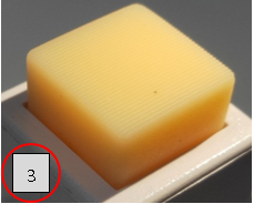
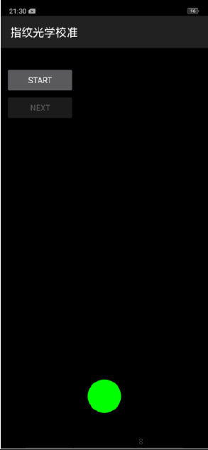
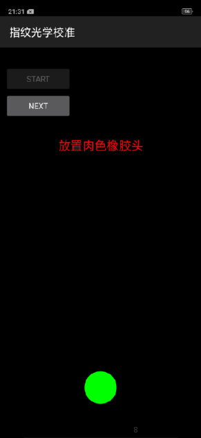
| Operation | 1、Make sure nothing cover phone, then press Infrared Proximity Calibration key | 2、After the screen infrared calibration, jump into the fingerprint optical calibration, click "START" to start calibration |
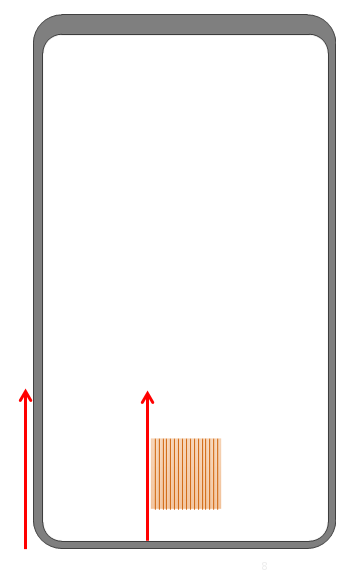
3、According to the prompt "Place the yellow rubber head(放置肉色橡胶头)", put the yellow rubber head on the fingerprint spot area (the groove is facing down), and click "NEXT" until the "Place black rubber head(放置黑色橡胶头)" is prompted to remove the yellow rubber head |
|---|---|---|---|
| Icon | 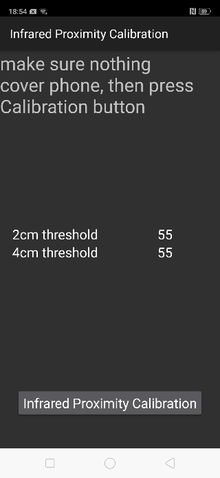 |
 |
 |
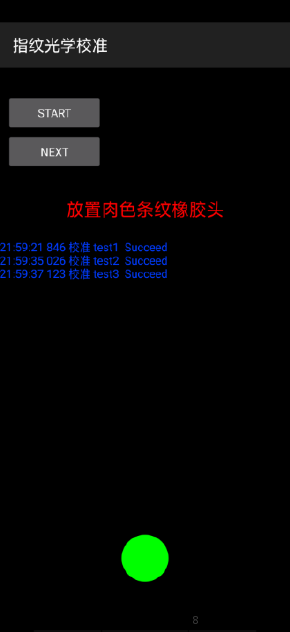
| operating | 4. According to the prompt "Place black rubber head(放置黑色橡胶头)", put the black rubber head on the fingerprint spot area (the groove is facing down), click "NEXT" until the "Place the yellow stripe rubber head(放置肉色条纹橡胶头)" prompts to remove the black rubber head; | 5. According to the prompt “Place the yellow stripe rubber head(放置肉色条纹橡胶头)”, put the yellow stripe rubber head (striped down) in the spot area, click “NEXT”; | 6. Prompt “Please exit when the test is completed(测试完成请退出)”, remove the yellow stripe rubber head and complete the test; If the prompt is fail, the test needs to be recalibrated again. |
| Icon | 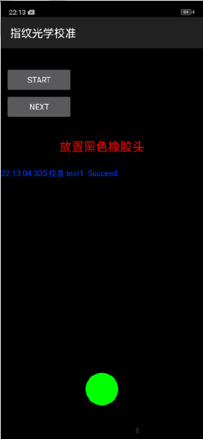 |
 |
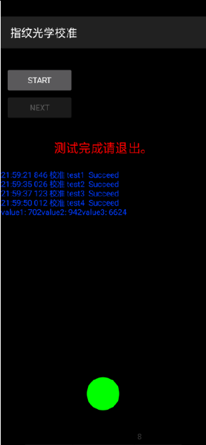 |
(1) The stripe direction of the yellow stripe rubber head should follow the long side of the phone.
(2) After the calibration is completed, the phone needs to be restarted for the calibration to take effect;
8. Post-maintenance functional test
After the repair is completed, first tested and identified the fault for the user. After the identification is completed, the basic functions of the mobile phone must be tested, and it can be returned to the user after passing the test.
8.1Visual inspection:
Check whether the mobile phone display screen is dirty or not; the mobile phone has no gaps, cracked shells, cracked keys, scratches, and whether the USB has fallen off etc.
8.2 Functional test path:
1) Input *#899# in the dial interface > automatic test > function test;
2) Input *#807# in the dial interface> enter the function test.
8.3 Testing requirements
| No. | Test Item | Test Requirement |
| 1 | LCD test | Click on the screen to switch among red, green, blue, white, black, gray, gray scale , multicolor, and fruit colors, cables, highlights, black spots, etc. |
| 2 | Vibration Test | The motor vibrates for 3 seconds, 1. Listen to the vibration noise. 2. Test whether there is no vibration or vibration weak, If there is the situation above, it is a defective product. |
| 3 | Touch screen auto test | If the interface jumps to the next test, the test is passed |
| 4 | Front camera preview | 1. For the white interface of the camera, detect whether there are black spots, black lines or blurred screen. 2. For the black interface, check whether there are bright spots, white spots or blurred screen; |
| 5 | Rear camera Preview | 1. For the white interface of the camera, detect whether there are black spots, black cables or blurred screen. 2. For the black interface, check whether there are bright spots, white spots or blurred screen; 3. For the interface with words, check whether the focus is clear |
| 6 | Second rear camera Preview | 1. For the white interface of the camera, detect whether there are black spots, black cables or blurred screen. 2. For the black interface, check whether there are bright spots, white spots or blurred screen; 3. For the interface with words, check whether the focus is clear |
| 7 | Echo test |
|
| 8 | Flashlight test | Check the function and color of the flashlight |
| 9 | Flash Charger | If the interface appears “PASS” and the interface automatically jumps to the next test, the VOOC Flash charge test is passed. |
| 10 | Headset in-out plug test | Insert the earphone in the earphone plug test. If the insertion is identified, the earphone test is passed. |
| 11 | Sensor self-test and calibration | Place the mobile phone flat on the desktop, click on the first calibration item. If it shows “PASS”, and automatically jumps to the next test item, it is without failure. |
| 12 | Gyroscope | After entering the test, take the mobile phone to draw the "8" word graphic. After the test OK, PASS will be displayed, and the next test item will be automatically jumped |
| 13 | M Sensor | Shake the phone from the left to the right side in the M Sensor in the test interface. After the test passes, it will automatically jump to the next test item and the M sensor is without failure. |
| 14 | Infrared Proximity Test(100mA) | Use the palm to cover the light sensor hole in the Proximity sensor test interface, and the screen will turn green from black. If the test is passed and the interface jump to the next test, the sensor is without failure. |
| 15 | Infrared Proximity Test(150mA) | Use the palm to cover the light sensor hole in the Proximity sensor test interface, and the screen will turn green from black. If the test is passed and the interface jump to the next test, the sensor is without failure. |
| 16 | Keypad test | Press the power Key, volume Key one by one. If the interface automatically jumps to the next test item without malfunction (if the Key is stuck or rising), the Key is with failure. |
| 17 | Finger print auto test | Automatic test OK will display PASS, automatically jump to the next test item |
| 18 | Media test | Check whether there is silence, weak sound, noisy sound, broken sound. If there isn’t failure with the speaker, it is passed. |
| 19 | Call test | Call the SIM card operator to check the receiver. If the call is normal without noise, weak sound, the receiver is without failure. |
| 20 | NFC test | After the mobile phone automatically selects the SIM1 simulation, Put the rear camera area of the mobile phone to close the NFC card reader, if the card reader signal light changes from red to green, and is accompanied by a "drop" sound, which is a good product.( The tool does not arrive or does not order the tool area temporary alternative: After entering the test interface, increase the volume of the mobile phone, put the label containing the chip into the rear camera area of the mobile phone, and the mobile phone emits a "drop" sound as a good product) |
| 20 | TOF test | Point the rear camera at the palm of your hand and see the palm outline. The TOF function is good and the camera interface will stay for 5 seconds. |
1. LCD Test
Inputting *#807# in the dial interface will automatically enter the LCD test of the function test. Click on the screen to switch among red, green, blue, white, black, gray, gray scale , multicolor, and fruit colors, cables, highlights, black spots, etc.
After the test is finished, the interface will automatically appear the “Confirm” dialogue box. If the LCD test fails, select “FAIL”. If the LCD test is passed, select “PASS”;If the result is confirmed, the interface will jump to the next test.
2. Vibration Test.
When the motor vibrates for 3 seconds, move the motor close to the ear. Test according to the above table. The “Confirm” dialog box will jump automatically after 3 seconds of the test. Select “PASS” if the test is passed. If there is noisy vibration, no vibration, or weak vibration, select "FAIL"
3 Touch Screen Automatic Test
The interface will jump to the touch screen automatic test after the last test was finished, and the mobile phone system will automatically test touch screen.
After the test is passed, it will automatically jump to the next test item; if the test fails, the interface will not jump. Press the return key to enter “Confirm” Dialog box, and select "FAIL";
Notice: Any replacement of screen or mainboard after sales must operate this step, or there will be abnormality: No function/Touch screen insensitivity/Disorderly touch point.
4. Front camera preview
After judging the result of the vibration, the Detection interface automatically entered for 5 seconds. Test according to the above test requirements. Judge the test result when the machine enters automatically “Confirm” dialog box after 5 seconds.
5. Rear camera preview
The Detection interface of main rear camera will be automatically entered for 5 seconds after judging the front camera. Test according to the above test requirements. Judge the test result when the machine enters automatically “Confirm” dialog box after 5 seconds.
6. Second rear camera preview
The Detection interface of sub rear camera will be automatically entered for 5 seconds after judging the main rear camera. Test according to the above test requirements. Judge the test result when the machine enters automatically “Confirm” dialog box after 5 seconds.
7. Echo test
In the echo test, if “Main MIC” is gray, the main MIC is being tested.;Blow the air to the MIC hole on the bottom of the phone. If the receiver (earphone) sounds, the test is passed; Then click on the " sub MIC" to test the sub MIC and blow air to the sub MIC hole on the top of the phone. If the speaker sounds, the test is passed. Press the return key to enter the “Confirm” dialog box and judge the result.
8. Flashlight test
The test interface of flashlight will be automatically entered for 5 seconds after judging the sub rear camera. Test according to the above test requirements. Judge the test result when the machine enters automatically “Confirm” dialog box after 5 seconds.
9. Flash Charger
Use the OPPO dedicated VOOC adapter and VOOC Line test. If the test is passed, it will automatically jump to the next test item. If the test fails, the interface will not jump. Press the return key to enter the “Confirm” dialog box and select "FAIL";
10. Headset in-out plug test
Enter the earphone plug-in test with the OPPO earphone and the interface will automatically jump to the next test item. If the test fails, the interface will not jump. Press the return key to enter the “Confirm” dialog box and select "FAIL";
11. Sensor self-test and calibration
When the phone enters into the Sensor self-calibration interface, the phone must be placed on the desk flatly. Then click the first calibration item. After the test is passed, it will automatically jump to the next test item; if the test fails, the interface will not jump. Press the return key to enter “Confirm” Dialog box, and select "FAIL";
12. Gyroscope
After entering the test, take the mobile phone to draw the "8" word graphic.
13. M Sensor
Shake the phone from the left to the right side in the M Sensor in the test interface. After the test passes, it will automatically jump to the next test item; if the test fails, the interface will not jump. Press the return key to enter “Confirm” Dialog box, and select "FAIL"
14 Infrared Proximity Test(100mA)
Use the palm to cover the light sensor hole in the Proximity sensor test interface, and the screen will turn green from black. If the test is passed and the interface jump to the next test, the sensor is without failure.
15 Infrared Proximity Test(150mA)
Use the palm to cover the light sensor hole in the Proximity sensor test interface, and the screen will turn green from black. If the test is passed and the interface jump to the next test, the sensor is without failure.
16 Key Test
Press the power Key, volume Key one by one. If the interface automatically jumps to the next test item without malfunction (If the key is stuck or rising, the Key is with failure).
17 Fingerprint auto test
Automatic test OK will display PASS, automatically jump to the next test item
18 Media Test
Check whether there is silence, weak sound, noisy sound, broken sound. If there isn’t failure with the speaker, it is passed.;
19 Call Test
If the phone has been installed with the operator's SIM card, dial the corresponding operator's phone number. If no card is inserted, call the 112 test (It is recommended to install the SIM card to call). Check according to requirements, press the return key to enter “Confirm” dialog box, and select the result of the judgment;
20 NFC Test
After the mobile phone automatically selects the SIM1 simulation, Put the rear camera area of the mobile phone to close the NFC card reader, if the card reader signal light changes from red to green, and is accompanied by a "drop" sound, which is a good product.( The tool does not arrive or does not order the tool area temporary alternative: After entering the test interface, increase the volume of the mobile phone, put the label containing the chip into the rear camera area of the mobile phone, and the mobile phone emits a "drop" sound as a good product)
21 TOF Test
Point the rear camera at the palm of your hand and see the palm outline. The TOF function is good and the camera interface will stay for 5 seconds.
After the above 21 test items are tested, they will prompt to the test result interface. If the test PASS, project will hit “√”; if the test FAIL, project will hit “×”. Items showing "X" need to be clicked again to test, until it is displayed as shown below
9. Precautions
1. If the repair process involves replacing the motherboard or disassembling the screen assembly/fingerprint module, the phone must be recalibrated;
2. After the installation is completed, it must be calibrated and tested to ensure normal use after maintenance;
3. If the mobile phone needs filming in the service center, the phone must be recalibrated after replacement;
4. Sensory test items require staff to judge the results. For example, LCD test, vibration test, pre-test, post-test, flash test, echo test, audio test, and call test are all human judgment results. Therefore, the judgment result must be followed. Test requirements judgment;
5. It is forbidden to use the return key to judge the result in advance if the test item is not tested.
------ Overseas Customer Service Technical Support Group
Ad
Sponsored Deals
Advertisement · Hand-picked offers, refreshed regularly
These are paid/affiliate advertisements from our partner store and are not related to OPPO or OPPO spare parts.
Related Articles
Ad
Sponsored Deals
Advertisement · Hand-picked offers, refreshed regularly
These are paid/affiliate advertisements from our partner store and are not related to OPPO or OPPO spare parts.