R17 Service Manual_V1

Content
1. Guidance
2. General Repair Information
3. Product Overview
4. Disassembly Steps
5. Assembly Step
6. Calibration
7. Function test
8. Cautions
1. Guidance
The purpose of this document is used to guide OPPO maintenance engineers to carry out service to OPPO products, and the content shall be keep in confidential. This Service Manual is to be used only by authorized OPPO maintenance service centers, not be provided to third parties for use without authorization. Please follow the regulations and follow the guidance for maintenance service, please contact HQ if any questions.
1.1 warnings and Cautions:
1.1.1 Warnings
1. Service centers may be required to install the handset's vehicle-mounted system in vehicles. Under certain fault conditions, the handset's RF signals may affect the operation of the vehicles' electric power management systems and anti–skid braking systems (ABSs). If necessary, consult the vehicle dealer/manufacturer to determine the immunity of vehicle electronic systems to RF energy.
2. The handset must not be operated in areas likely to contain potentially explosive atmospheres, such as petrol stations, gas stations and blasting areas.
3. Operation of any radio transmitting equipment, including handsets, may interfere with the functionality of the medical devices protected by industrial mechanisms. Consult the manufacturer of the medical device if necessary. Other electronic equipment may also be subject to interference.
1.1.2 Cautions
1. Maintenance and calibration must be undertaken by qualified technicians only.
2. Use only the materials listed in the BOM for maintenance services.
3. All parts are assembled correctly as required.
4. Electrostatic discharge can easily damage the sensitive components of electronic products. Service centers must follow with OPPO's requirements for electrostatic protection. All the operations must be on an ESD maintenance table and worn with an ESD ring.
2. General Repair Information
1.Before starting the maintenance, please enter the ESD area and wear the ESD ring.
2. ESD gloves are recommended to avoid oil stains and fingerprints.
3. Use protective film to protect the display screen, camera, and camera lenses from dust and scratches.
4. It is necessary to use dust-free cloth, ESD brush and alcohol (concentration above 95%) for appearance cleaning. Do not use other items for cleaning (like eraser) to prevent the protective layer on the scratched surface from oxidizing and corroding.
5. It can only be replaced instead of repair if the welded mechanical parts (except the shield cover and shield frame parts) fail.
6. Repairs must be made using the accessories supplied by OPPO.
7. Check the contacts or solder joints of devices that may cause simple faults (e.g. soldered connectors or switches) and re-solder them if necessary (only repair centers that can conduct lead-free soldering) and clean the residual flux after welding.
8. You must use the equipment provided by OPPO to test whether the mobile phone is normal. For example, if the customer feedback charging malfunction, please use the original adapter of OPPO to test to ensure the accuracy of test results.
9. When recording the fault code in the after-sales system, fill in the fault phenomenon code and fault reason code according to the actual situation, and accurately record the replacement accessory code (refer to " Smart Phone Fault Reason Code List " if necessary).
10. If you want to know more information about this product, please visit the FTP service: ftp://ftpex.oppo.com:919/
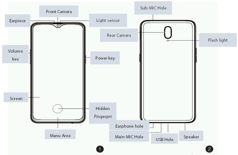
3. Product Overview
3.1 Product Appearance:
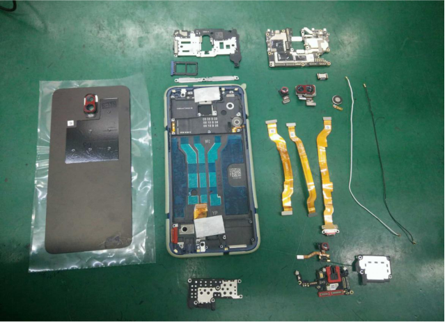
3.2 Exploded View of Phone’s Structure
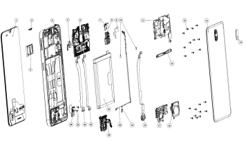
3.3 Exploded map corresponding material table
|
NO. |
Material name |
Picture |
Model specification |
Unit |
Number |
|---|---|---|---|---|---|
|
1 |
OLED Display Screen |
|
AMS641RW01-0 |
PCS |
1 |
|
2 |
Receiver Dustproof net |
/ |
AD028 Single Glue |
PCS |
1 |
|
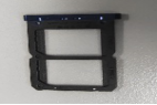
3 |
SIM Card Holder |
|
AD062 Red &Purple Gradient Aluminum alloy |
PCS |
1 |
|
4 |
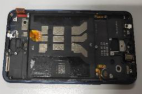
Middle frame |
|
AD062-2 Red&Purple Gradient Aluminum alloy With Padding |
PCS |
1 |
|
5 |
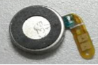
Vibration Motor |
|
Φ10×2.5 3V 32Ω 8mm(Ring), Welding-FPC(Without Glue) |
PCS |
1 |
|
6 |
FPC semi-finished product |
|
2AD027-0 18085 |
PCS |
1 |
|
7 |
Camera (Front) |
|
IMX576 25.0MP 7.7×7.82×4.91 5P BTB CMD479 |
PCS |
1 |
|
8 |
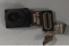
Camera (Rear) |
|
IMX519+5E9 16.0M+5.0M 19.05×11.7×5.81 6P+3P BTB OJS1154 |
PCS |
1 |
|
9 |
Camera graphite flake(font) |
/ |
AD028 Black |
PCS |
1 |
|
10 |
Waterproof padding for key |
|
AD028 black PORON single side glue |
PCS |
1 |
|
11 |
Motherboard pressing plate bracket |
|
AD028 Black |
PCS |
1 |
|
12 |
Machine-tapping screw |
/ |
CM 1.4×2.8 White nickel (Head Diameter2.5,Head Thickness 0.4) Anti loosening 2# |
PCS |
21 |
|
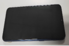
13 |
Battery Cover |
|
AD062 Red&Purple Gradient Glass With Padding |
PCS |
1 |
|
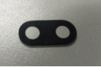
14 |
Camera Lens |
|
AD028 Black GG5/ Sapphire |
PCS |
1 |
|
15 |
Motherboard BTB plate support |
|
AD028 Stainless steel |
PCS |
1 |
|
16 |
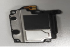
Speaker |
|
1.5W 3.82×20.2×23.83mm BOX G |
PCS |
1 |
|
17 |
Antenna plate support |
/ |
AD062 Stainless steel 2# |
PCS |
1 |
|
18 |
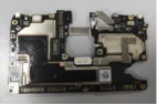
PCB Semi-finished Product |
|
UAD027-1-Patch 18081 |
PCS |
1 |
|
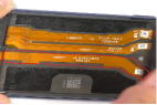
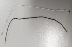
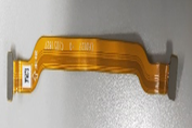
19 |
RF Connection Cable |
|
50Ω 165mm 8MM5Q2BG10000001S5(φ0.64) |
PCS |
1 |
|
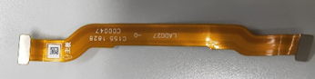
20 |
RF Connection Cable |
|
50Ω 178mm 8180(Φ0.64) |
PCS |
1 |
|
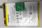
21 |
Lithium Battery |
|
@3415/3.85V/1.5C BLP681 406578 DA B790 |
PCS |
1 |
|
22 |
PCB Semi-finished Product |
|
AAD027-0 18081 |
PCS |
1 |
|
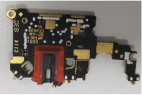
23 |
PCB Semi-finished Product |
|
CAD027-0-Patch AD027 |
PCS |
1 |
|
24 |
PCB Semi-finished Product |
|
LAD027-0-Patch AD027 |
PCS |
1 |
|
25 |
Machine-tapping screw |
|
CM 1.2×1.8 Black Nickel (Head Diameter2.2,Head Thickness 0.3) Anti loosening 2# |
PCS |
2 |
|
26 |
Fingerprint sensor module |
|
GSL7000A1 8.71*3.83*3.03 BTB AD028 B731 UD B731 UD Black |
PCS |
1 |


Note: This table is used only for the name of the annotation. It is not suitable for the preparation of materials. Please refer to the “Price list of Commonly-used Materials and Accessories” for the preparation.
4. Disassembly steps
4.1 Disassembly tools required as shown below:
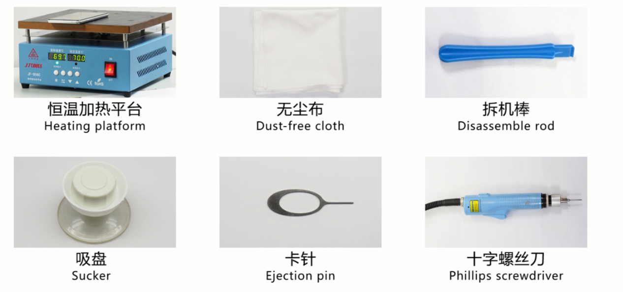
4.2 Preparation
1. The phone must be shut down with the power option before disassembling.
2. Way to Shut Down: Press the power button then slide to power off.( The forced shutdown method is long press the volume + button and power button for about 8 seconds until the display is off)
4.3 Disassembly Steps
|
Steps |
Details |
Picture |
Cautions |
|---|---|---|---|
|
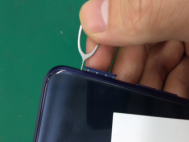
1 |
Remove the SIM card holder |
|
Do not scratch the appearance |
|
2 |
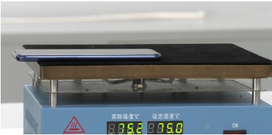
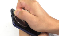
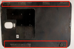
Remove the battery cover |
|
1. Place the battery cover face down and heat it at 75 c for 2-4min. |
|
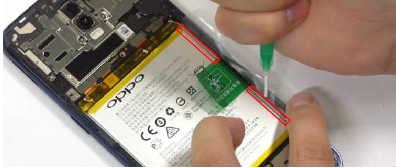
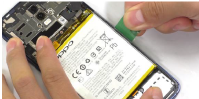
3 |
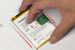
Remove the battery |
|
Be careful not to deform the battery 2.Check for puncture, indentation, leakage and other defects after removing the battery |
|
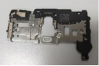
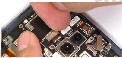
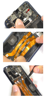
4 |
Remove the mainboard and camera |
|
Be careful not to damage the RF socket on the motherboard |
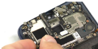
|
5 |
Remove L-board, U-board, RF cable and speaker |
|
Be careful not to damage the RF socket on the antenna board |
|
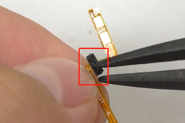
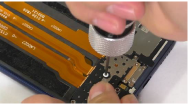
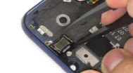
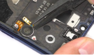
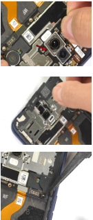
6 |
Remove small board, sound box and fingerprint module |
|
Since there is no screen fingerprint function in the Singapore area, it is implemented by software function, but the fingerprint hardware still exists under the screen. The Singapore regional machine also needs to operate according to the following disassemble steps. |
|
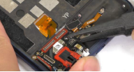
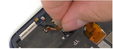
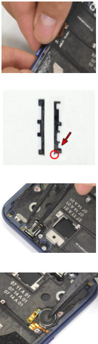
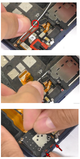
7 |
Disassemble receiver , motor and side key FPC |
|
/ |
|
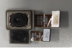
All the parts are as shown |
|
||
5. Assembly Step
5.1 Materials are required to be replaced after disassembly
|
NO |
Material name |
Specification |
Picture |
Remark |
|---|---|---|---|---|
|
1 |
battery pull tape |
BLP707 transparent |
|
|
|
2 |
Battery cover double-sided adhesive |
CC122 black |
|
|
|
3 |
All auxiliary materials, including double-sided adhesive tape, graphite sheet, copper foil, conductive cloth, foam |
|
/ |
|
5.2 Assembly Step
|
NO |
Details |
Picture |
Cautions |
|---|---|---|---|
|
1 |
Install Power key& Receiver& Motor |
|
(1)Insert the power key, press the power key to press the power key FPC, and then insert the power key bracket to fix it. Note that when the power key bracket is installed, the buckle faces the bottom of the phone, and the bracket is pressed tightly to ensure that the bracket does not tilt, according to the positioning. The position of the column is to put the power key FPC on the double-sided tape of the middle frame, and press it with the tweezers to ensure closeness and compaction; the volume key is installed as above. |
|
2 |
Install Fingerprint module, antenna board and speaker |
|
(1)Place the fingerprint module in the fingerprint slot, press it slightly to fit it in the slot, and use the screwdriver to fix the fingerprint module screws (note that the fingerprint module screw is 2 black screws); |
|
3 |
Install RF cable on the antenna board end, L board, C board, U board and antenna board bracket |
|
(1)When the white RF cable is installed, (the end of the metal ring is the end of the antenna board); the black RF cable is not distinguished. When the RF cable is installed, the RF head is pressed vertically into the RF holder and cannot be tilted. After assembly, gently buckle the RF head to confirm that the RF head is buckled. Then in turn the wire into the small plate end slot; |
|
4 |
Install motherboard, FPC, RF cable and motherboard |
|
(1)Install the motherboard from the left to the right and tilt it down. Pay attention to the edge of the motherboard and do not force it. Insert the right side of the motherboard and press the motherboard so that it does not tilt and insert the SIM card holder. |
|
5 |
Install camera, motherboard plate support and side key FPC sealed foam |
|
(1)Tilt the front camera to confirm that the BTB buckle is vertically pressed after the flat position. |
|
6 |
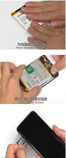
Install Battery, BTB press plate and battery cover |
|
(1)Replace the battery with a new easy-tore paper to ensure that the easy-tore paper fits and is flat. After checking the bottom of the battery compartment without foreign matter, buckle the battery BTB buckle, and confirm that the buckle is not loose, put the battery into the battery compartment to ensure the battery is placed correctly. Afterwards, press it by hand to make it fi |
6. Calibration
Note: Since there is no screen fingerprint function in the Singapore area, it is implemented by software function, but the fingerprint hardware still exists under the screen, so there is still a fingerprint module component in the machine.
1.The Singapore regional machine does not need to perform on-screen fingerprint calibration;
2.Other areas of the machine need to do the screen fingerprint calibration as follows.
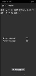
Enter the calibration interface path:Dial interface input > *#899# >AfterSale Devices Calibration> enter password “6776” >Infrared Proximity Calibration > Fingerprint calibration,Specific operations refer to calibration page hints:
|
Operation |
1、Make sure nothing cover phone, then press Infrared Proximity Calibration key |
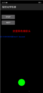
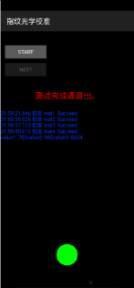
2、After the screen infrared calibration, jump into the fingerprint optical calibration, click "START" to start calibration |
3、Press the flesh-colored rubber head (the groove is facing down) according to the prompt "Place the flesh-colored rubber head". |
|
Icon |
|
|
|
|
operating |
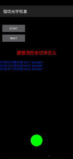
4. According to the prompt "Place black rubber head", press the black rubber head on the fingerprint spot area (the groove is facing down), click "NEXT" until the "Place the flesh-colored stripe rubber head" prompts to remove the black rubber head; |
5. According to the prompt “Place the flesh-colored stripe rubber head”, press the flesh-colored stripe rubber head (striped down) in the spot area, click “NEXT”; |
6. Prompt “Please exit when the test is completed”, remove the flesh-colored stripe rubber head and complete the test; |
|
Icon |
|
|
|


7. Function test
7.1 Test Path
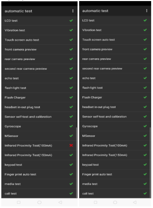
Dialing Interface>Enter*#899#>Enter automatic test; The "Confirm" dialog box will pop up after the test complete, if there is no problem choose “Pass”, otherwise choose “Fail”.
7.2 Test Requirements
|
No. |
Test Item |
Test Requirement |
|---|---|---|
|
1 |
LCD test |
Observe the red, green, blue, white, black, gray, grayscale and color interface successively; If there are black spots, bright spots and other anomalies, the function is sound; |
|
2 |
Vibration Test |
Get ear close to check the vibration from the motor for 3 seconds. |
|
3 |
Touch screen auto test |
If the interface shows “PASS” and jumps to the next test, the function is sound; |
|
4 |
Front camera preview |
Align the front camera with a white surface and a black surface. If there is no black dot, black line or blurred screen on the screen after aligning the white surface, and there is no bright spot on the screen after aligning the black surface, the camera is sound; |
|
5 |
Rear camera Preview |
Align the rear camera with a white surface, a black surface, and a surface with text. If there is no black dot, black line or blurred screen on the screen after aligning the white surface, there is no bright spot on the screen after aligning the black surface, white point or blurred screen, the camera is sound; |
|
6 |
Second rear camera Preview |
Align the rear camera with a white surface, a black surface, and a surface with text. If there is no black dot, black line or blurred screen on the screen after aligning the white surface, there is no bright spot on the screen after aligning the black surface, white point or blurred screen, the camera is sound; |
|
7 |
Echo test |
Testing Main MIC: Blow the air to the MIC hole on the bottom of the phone. If the receiver (earphone) sounds, the function of Main MIC is sound; |
|
8 |
Flashlight test |
Open the flashlight. If it can be opened normally with color deviations, the function is sound; |
|
9 |
Flash Charger |
Use the original OPPO adapter and USB cable to charge. If the interface shows “PASS” and jumps to the next test, the function is sound; |
|
10 |
Headset in-out plug test |
Plug in and out the earphone with the OPPO earphone. If the interface shows “PASS” and jumps to the next test, the function is sound; |
|
11 |
Sensor self-test and calibration |
When the phone enters into the Sensor self-calibration interface, the phone must be placed on the desk flatly. Then click the first calibration item. After the test is passed, it will automatically jump to the next test item |
|
12 |
Gyroscope |
Take the mobile phone to draw the "8" word graphic. If the interface shows “PASS” and jumps to the next test, the function is sound; |
|
13 |
M Sensor |
Shake the phone from the left to the right side. If the interface shows “PASS” and jumps to the next test, the function is sound; |
|
14 |
Infrared Proximity Test(100mA) |
Use the palm to cover the light sensor hole, and the screen will turn green from black. If the interface shows “PASS” and jumps to the next test, the function is sound; |
|
15 |
Infrared Proximity Test(150mA) |
Use the palm to cover the light sensor hole, and the screen will turn green from black. If the interface shows “PASS” and jumps to the next test, the function is sound; |
|
16 |
Keypad test |
Press the power key and volume key one by one. If keys can be pressed normally and the interface jumps to the next test, the function is sound; |
|
17 |
Finger print auto test |
Automatic test OK will display PASS, automatically jump to the next test item |
|
18 |
Media test |
Click the “20-4K(-3db)signal” to test the sound of the media function for 5s. If there is no silence, weak sound, noises, and breaking sound, the interface shows “PASS” and jumps to the next test, the function is sound; |
|
19 |
Call test |
If the phone has been installed with the operator's SIM card, dial the corresponding operator's phone number. If no card is installed, call the 112 to test (Calling the Operator is recommended). If the call can be performed normally and the receiver is without noises or weak sounds, the function is sound; |
After the above 19 test items are tested, they will prompt to the test result interface. If the test PASS, project will hit “√”; if the test FAIL, project will hit “×”. Items showing "X" need to be clicked again to test , until it is displayed as shown below
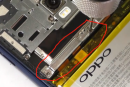
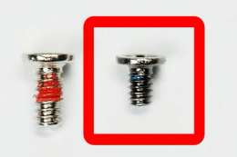
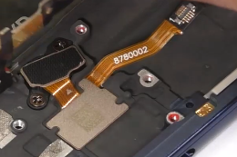
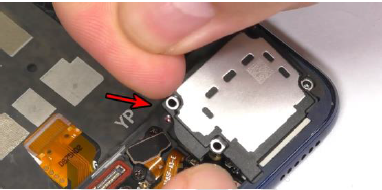
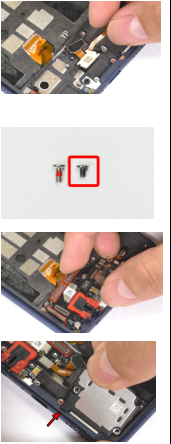
8. Cautions
There are two kinds of screw materials in R17, as shown in Figure 8-1. The position of the small screws (2 in total) is circled in the yellow circle in Figure 8-2. The position of the large screws (21 in total) is shown in Figure Circle red circle in 8-2. ( Do not mix screws)

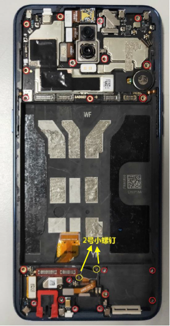
Figure 8-1 Figure 8-2
1. Recalibration is required after maintenance.
2. After assembly, calibration must be performed before functional testing to ensure proper function after maintenance;
3. Sensory test items require staff to judge the results. For example, LCD test, vibration test, pre-test, post-test, flash test, echo test, audio test, and call test are all human judgment results. Therefore, the judgment result must be followed. Test requirements judgment;
4. It is forbidden to use the return key to judge the result in advance if the test item is not tested.
------ Overseas Customer Service Technical Support Group