Service Center Repair Tool Instruction Manual _V1
|
Version |
Date |
Modified by |
Verified by |
Approved by |
Modified content |
|
V1.0 |
2020-2-12 |
Guohua Chen |
Xinnan Li |
Guoxin Huang |
1.First edition |
1.Overview
Sharp tools make good work.
Mastering the usage of mobile phone repair tools is the basis for repairing mobile phones, and the proficiency determines the quality and speed of mobile phone repairs. This instruction manual is intended to help maintenance personnel master the operation methods of maintenance tools and related specifications for maintenance.
2.6S
The static electricity is harmful during the repair, the breakdown or damage of chips and other components are directly related to static electricity.
ESD (Electrostatic Discharge) means "electrostatic discharge". Internationally, the equipment used for electrostatic protection is collectively referred to as ESD, and we also call it electrostatic impedance device.
There are three ways to protect against the static electricity: preventing the accumulation of static charge; establishing a safe release path; monitoring the effectiveness of all anti-static measures in real time. Here are some common ESD protection tools and methods.
2.1 Ion fan
2.1.1 Background
The climate in some regions is dry, so the static index of the service center's repair environment does not meet the company's requirements. Therefore, the company will provide ion fans (tool code: 535481083) for customer service centers in some regions. The ion fans can quickly eliminate static electricity in the repair environment, and effectively prevent static electricity from damaging components, which can improve the repair level and quality of customer service centers.
2.1.2 Involved scenes
Ion fans are used to remove static electricity during the repair when holding materials by hand in customer service centers.
2.1.3 Content
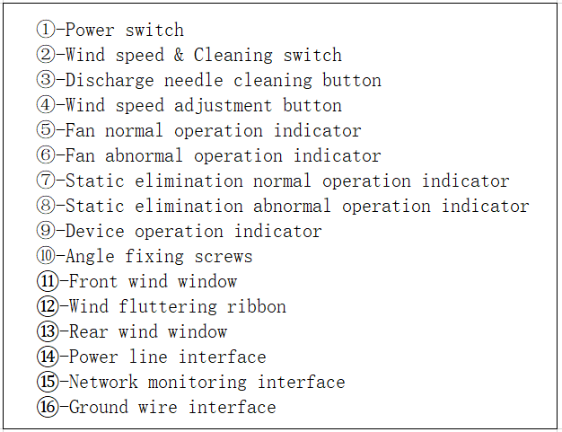
1. Ion fan functions introduction, as shown in Figure 2-1.
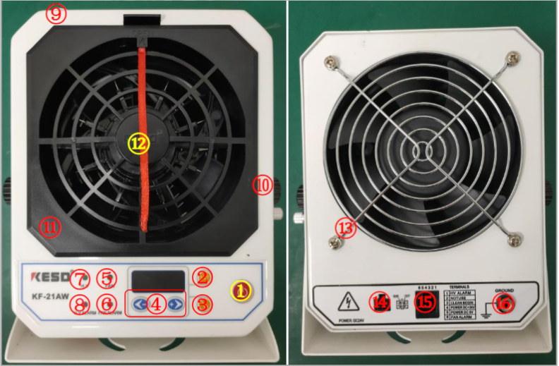
Figure 2-1 functions introduction
2. Installation
There is a buckle on the connection end of power line interface, which needs to be locked in place to prevent the device from malfunctioning due to poor contact. Before the ion fan is in use, it must be connected to the ground wire (One end is connected to the device, and the other end is connected to the ground wire with an alligator clip) to improve the safety of the device, as shown in Figure 2-2.
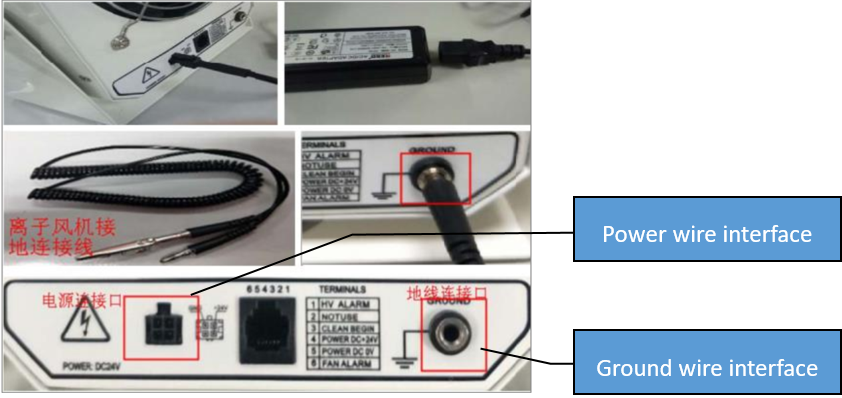
Figure 2-2
3. Placement
The ion fan is placed in the upper left corner or the upper right corner of the table, and it is placed at 45 ° from the table side, as shown in Figure 2-3. By adjusting the angle fixing screw, keeping the air outlet tilted forward about 15 °,so that the airflow from the ion fan can cover the operation area of anti-static mat and material storage area.
Figure 2-3 placement for ion fan
4. Parameters settings
1) Wind speed setting. During the repair, the wind speed of the ion fan should be adjusted to F-01, as shown in Figure 2-4. It can be adjusted by the “-” and “+” buttons to increase the wind speed.

Figure 2-4 parameters setting
2) Scheduled cleaning settings. Scheduled cleaning time should be set to 3 hours, The ion fan will continue to run for 3 hours without interruption, then the program will automatically start to clean the internal discharge needle ( turn off the power switch of the device, the 3-hour-time will be recalculated ). The operation steps of the regular cleaning settings are shown in Figure 2-5: Press the "SET" button, the display will switch from wind speed “F-01” to timing interface (H034 means 34 hours); then pressing the "SET" button can switch between the three-number ( such as 034 ), and press “-” or “+” button to adjust the number; the timing should be set to 3 hours, the screen will display H003, then click the “SET” button, the interface will display the wind speed, that means the timing setting is done.
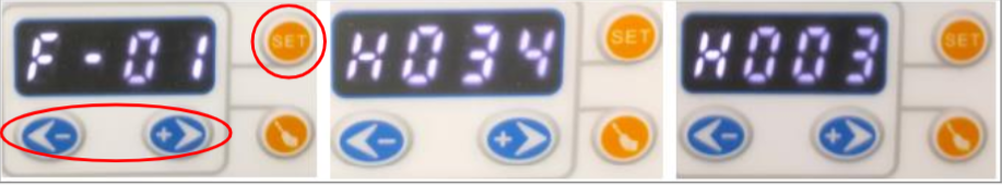
Figure 2-5 timing setting
5. Maintenance
The maintenance of the ion fan mainly includes the cleaning of the discharge needle, the dust removal of the front and rear windows and the internal fan blades. Remove the power line to cut off electricity during maintenance. You need to remove the front and rear windows for cleaning and dust removal every month, the steps are shown in Figure 2-6.
1) Power off the ion fan, remove the front wind window, and clean the dust (5PIN metal shrapnel and brush head, which can be cleaned with a clean cloth and alcohol).
2) Remove the discharge needle by turning it counterclockwise, use an anti-static brush to clean the dust, and clean the needle with a dust-free cloth moistened with alcohol ( be careful of the sharp discharge needle ).
3) Remove the rear wind window with a Phillips screwdriver, wipe it with a cloth or clean it with an anti-static brush.
4) Use an anti-static brush to clean the internal structure (if the surface of the 5PIN metal shrapnel is oxidized, it can be cleaned with a dust-free cloth and alcohol after being scraped), and finally pour out the dust from the ion fan.
5) Assemble the parts in order, and test each function to make sure the ion fan can work normally.
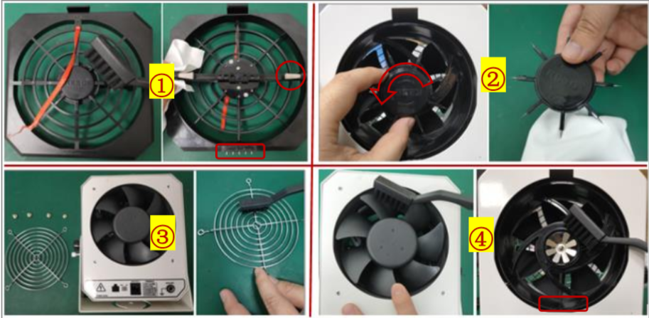
Figure 2-6 maintenance steps
2.1.4 Frequently Asked Questions (FAQ)
1) The "static elimination abnormal operation indicator" is on and the buzzer sounds, what should I do?
The "static elimination abnormal operation indicator" is on, indicating that the static-removing function is abnormal, which has a great relationship with the discharge needle. You must first remove the power cord of the device, the front wind window, the discharge needle and clean it (refer to step 4 and 5 Ion Fan Maintenance). If the fault is not resolved, replace the discharge needle with a new one.
2) Ion fan does not work, how to troubleshoot the device?
According to the information provided by the supplier and the internal use of the company, the most common causes of failure are: the high voltage regulator and iron oxide in the rack are bad, the front windshield is badly contacted, and the motherboard circuit is bad. Maintenance engineers can only perform maintenance on the front wind window, first unplug the power cord of the device to cut off the power, then clean the 5PIN metal connection between the front wind window and the main body of the device (see steps 4 and 5 Ion fan maintenance), and finally replace front window.
2.1.5 Cautions
1. It is forbidden to use in the flammable and explosive environment, and it is only allowed to use in the maintenance room of the customer service center.
2. Check the grounding of the ion fan carefully before turning on the power switch.
3. Do not insert foreign objects into the wind window. Do not touch the discharge needle of the ion fan with metal wires during normal operation of the ion fan.
4. The airflow blown by the ion fan has a large amount of positive and negative charges. It is strictly prohibited to blow directly to the head of the repair engineers.
5. When the ion fan sounds an alarm or other abnormal situation, cut off the power immediately and isolate it, and notify the technical teams to deal with it.
6. The ion fan must be turned on during the repair (the ion fan can be temporarily turned off when engineers do not repair), and cut off the power manually after work. This item will join the professional 6S assessment. If the indicator light is off or the ribbon is still, it will be judged as a 6S violation.
2.2 Temperature and humidity meter
2.2.1 Background
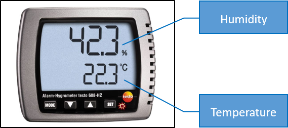
The company has strict requirements for the repair environment of the customer service center. The humidity and temperature in the repair room must meet the company's maintenance standards. So the company provide temperature and humidity meter (code: 535480401), which is used to continuously measure air temperature and ambient humidity.
2.2.2 Involved scenes
For continuous measurement and display of current temperature and humidity values, real-time monitoring of the indoor environment of the service center repair room.
2.2.3 Content
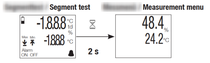
1. Connect battery (ensure polarity is correct), wait for 2s, then the measurement menu appears.
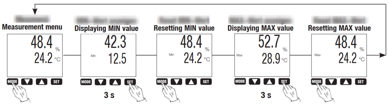
2. Press the "MODE" button to display the Max/ Min value.
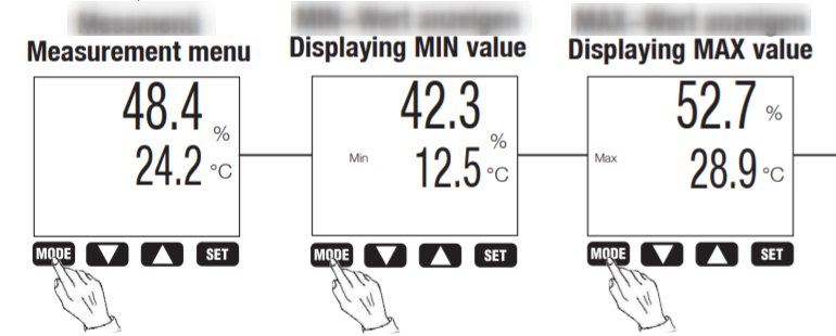
3. Resetting Max/Min value (Hold down the "SET" button for 3s to reset the Max and Min value, and press the "MODE" button to return to the measurement mode).
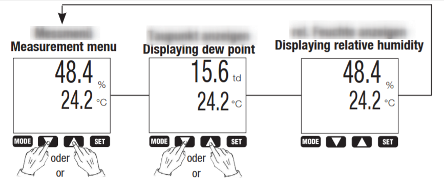
4. Setting parameters (td, %RH)
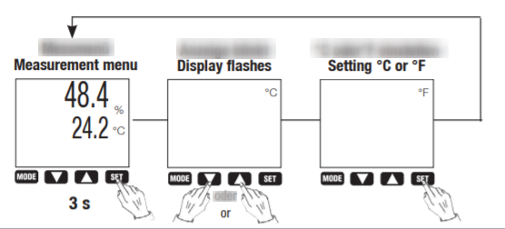
5. Setting parameters (°C, °F)
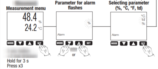
6. Activating/deactivating the alarm
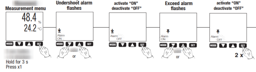
7. Select parameter for alarm (%, °C, °F, td)
%—Humidity; °C—Celsius; °F—Fahrenheit; td—Dew point
8. Setting limit values for alarm (Condition:  is activated)
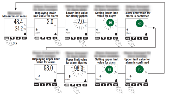
Note: Customer service center repair room environment requires humidity of 40% ~ 75% RH and temperature of 18°C ~ 28°C. If this standard is not met, we should add a humidifier to increase the humidity in the air of the repair room.
2.3 Anti-static wrist strap
2.3.1 Background
Grounding is very important to reduce the electrostatic charge on the conductors. The human body is a conductor and also the main source of static electricity. Therefore, it is necessary to reduce the electrostatic charge generated by people who touch sensitive electronic components during the repair.
In daily mobile phone repair, anti-static wrist strap (tool code: 535481083) is the most commonly used grounding device, which can safely and effectively remove static charges from the human body. Only by touching the skin can the anti-static wrist strap work well. A dirty or loose antistatic wrist strap may retain the static charge that has been leaked, making the antistatic control ineffective.
2.3.2 Involved scenes
Engineers must wear anti-static wrist straps when servicing mobile phones in order to protect against static electricity.
2.3.3 Content
1. Anti-static wrist, as shown in Figure 2-7
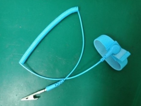
Figure 2-7
2. Keep the antistatic wrist strap clean and free of foreign objects, and keep the wrist strap close to the skin when wearing, as shown in Figure 2-8; the alligator clip ground terminal must be connected to the bare copper wire of the ground line, as shown in Figure 2-9.
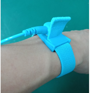
Figure 2-8
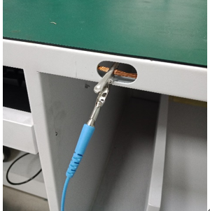
Figure 2-9
3. Disassembly tools
The first step in repairing process is to disassemble the phone. You must understand the use of various tools and master the key disassembly and assembly skills.
3.1 Constant temperature heating platform
3.1.1 Background
Engineers in customer service centers used hot air to heat the battery back cover, which can cause uneven heating of the battery cover. Therefore, the constant temperature heating platform is used to heat the battery cover of the R15 / R15 dream mirror version and subsequent listed models. After uniform heating, it better assists repair engineers to disassemble the battery cover.
3.1.2 Involved scenes
Heating the battery cover that add adhesive to assemble, such as R15 series.
3.1.3 Content
1. Function introduction of constant temperature heating platform, as shown in Figure 3-1.
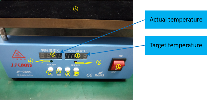
Figure 3-1
2. Setting working temperature
Turning on the power switch, pressing the "⑧" button, setting the "target temperature" to 80 °C, and then pressing the "⑦" button to confirm and exit.
3. The heating indicator light flashes, the heating platform starts to heat up, and the "actual temperature" value rises, as shown in Figure 3-2.
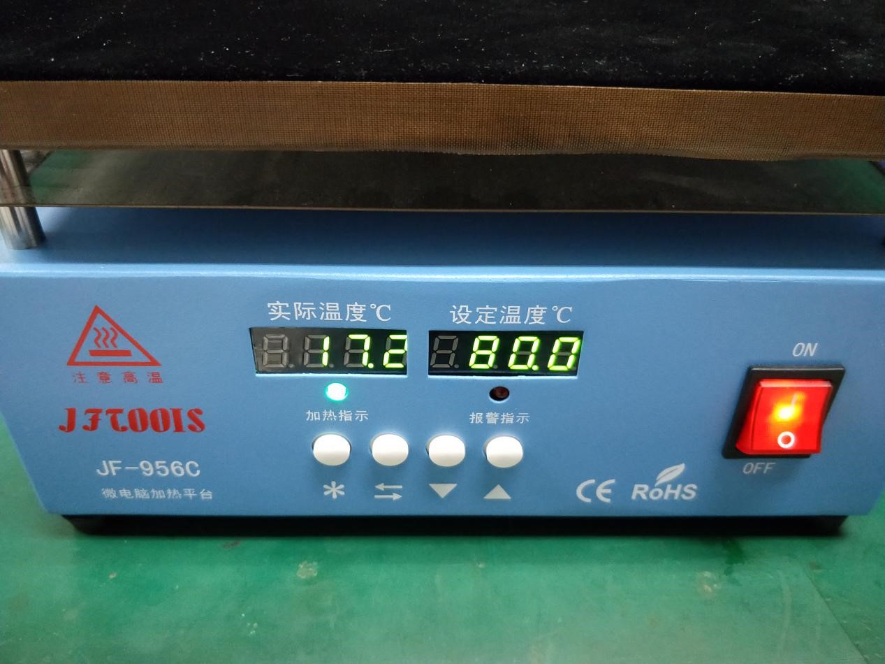
Figure 3-2
4. When the "actual temperature" value reaches the "target temperature" (80 °C), the heating indicator light turns off; then place the phone on the heating platform, as shown in Figure 3-3, turn off the power of the device after heating for 5 minutes, and start to disassemble the battery cover.
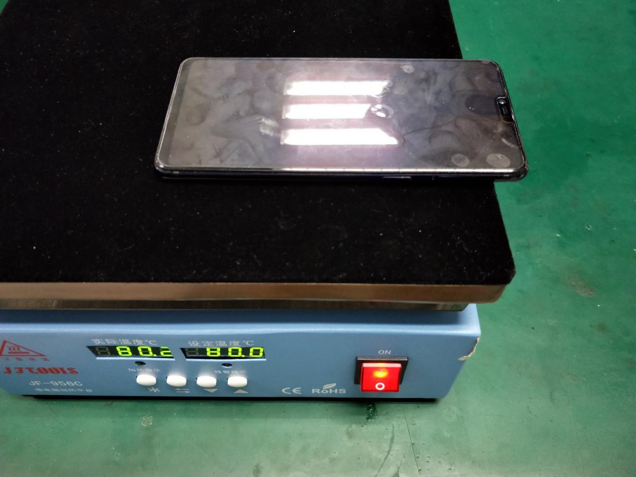
Figure 3-3
3.1.4 Maintenance
1. Temperature calibration
The default maximum temperature of the heating platform is 95 °C. When the temperature displayed by the machine deviates from the actual temperature, we need to calibrate temperature manually. For example, the “actual temperature” displayed is 80 °C, but the measured temperature is 85 °C. The operation method is as follows:
Press "⑦" and "⑩"button at the same time, "CAL" will be displayed in the "Actual Temperature" window, enter the actual measured temperature of 85 °C in the "target temperature" window, and press "⑦" again to confirm the calibration.
2. Over-temperature protection
When the temperature sensing device or temperature control system of the equipment is abnormal, in order to protect the equipment from being damaged by abnormal heat, the machine is equipped with an automatic power-off switch at 100 °C. Common performance are: the power switch will light normally, but the temperature display window will be not displayed. When the temperature drops below 100 °C, the machine functions normally again.
3.1.5 Cautions
1. Do not use this heating platform in a flammable, explosive, high temperature environment.
2. When the equipment is working, the heating surface is hot. Do not touch the heating surface with your hands or body parts to prevent burns.
3. Turn off the equipment in time after finishing heating to avoid scalding when you accidentally touch it.
4. When the alarm indicator light is on or there are other abnormal conditions on the device, turn off the power and isolate it in time, and notify the company's technical team to deal with it.
3.2 Sucker
3.2.1 Background
After R9, the battery covers of most models use double sided adhesive to assemble. After heating, it is necessary to separate the battery cover with a sucker when disassembling.
3.2.2 Involved scenes
For adsorbing the battery cover and pulling it apart after heating.
3.2.3 Content
1. The correct installation method of the sucker (tool code: 535449537) is shown in Figure 3-4.
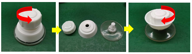
Figure 3-4 Installation of sucker
2. After heating, use the sucker to adsorb the battery cover, then slowly pull up the gap, and then use the disassemble card to remove it c, as shown in Figure 3-5.
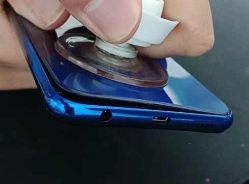
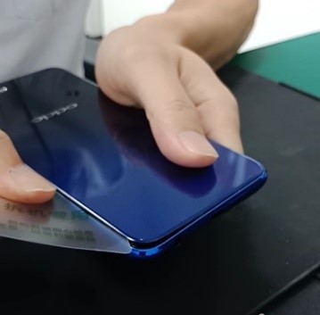
Figure 3-5
3.3 Disassemble rod
3.3.1 Background
The battery covers of most models use double sided adhesive to assemble. When disassembling the battery cover, we need to use disassemble rod or disassemble card to help with it.
3.3.2 Involved scenes
Assisting in disassembling the battery cover after heating. The appearance of the disassemble rod (tool code: 535045136) as shown in Figure 3-6, or disassemble card (tool code: 5353003734) as shown in Figure 3-7.
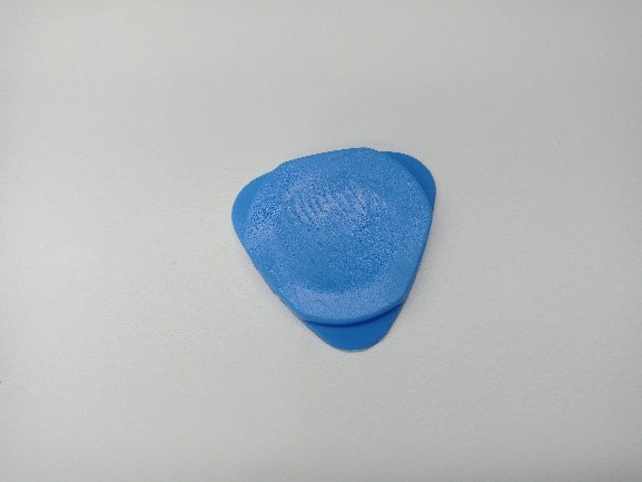
Figure 3-6
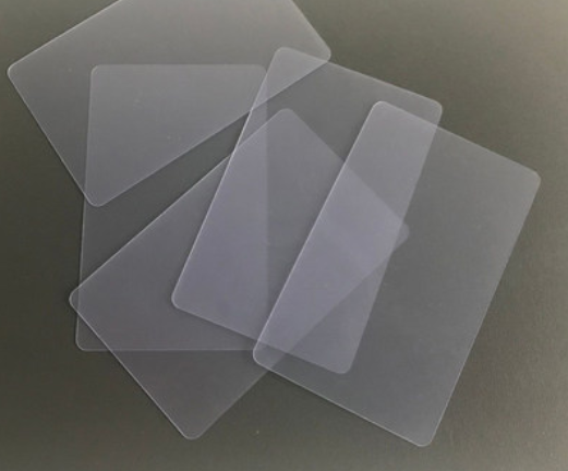
Figure 3-7
3.3.3 Content
1. Use the sucker to pull out a gap, as shown in Figure 3-8.
2. Hold the phone with your index finger and thumb in your right hand and hold your phone firmly with your left hand.
3. Insert the disassembly rod or disassembly card into the gap, then slide it gently. Add appropriate alcohol to the position, wait for a while, and then continue sliding until the battery cover is separated from the middle frame of the phone, as shown in Figure 3-9 or Figure 3-10
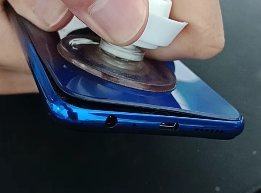
Figure 3-8
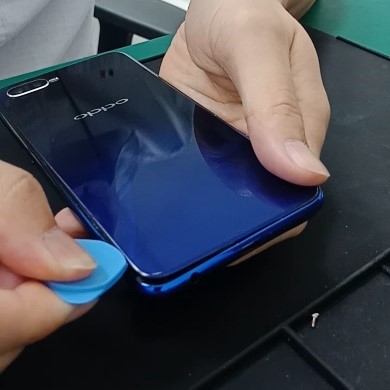
Figure 3-9

Figure 3-10
3.4 Teardown rod
3.4.1 Background
For some part of the models, their battery covers are snap-fitted, so special tool is required to disassemble the battery cover.
3.4.2 Involved scenes
Teardown rod is used for (tool code: 535045234) disassembling the battery cover that is snap-fitted.
3.4.3 Content
1. The following tools are required to disassembling the snap-fitted battery cover:
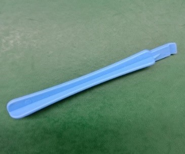
Figure 3-11 teardown rod

Figure 3-12 Card needle

Figure 3-13 Dust-free cloth
2. Disassembly steps
1) Turn off the phone first, and then remove the tray with the card needle, as shown in Figure 3-14.
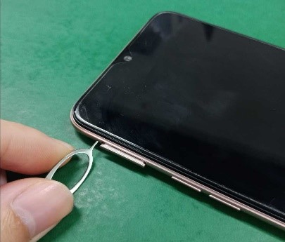
Figure 3-14
2) Check if there are screws on the bottom of the phone. If so, remove the screws with screwdriver, as shown in Figure 3-15.
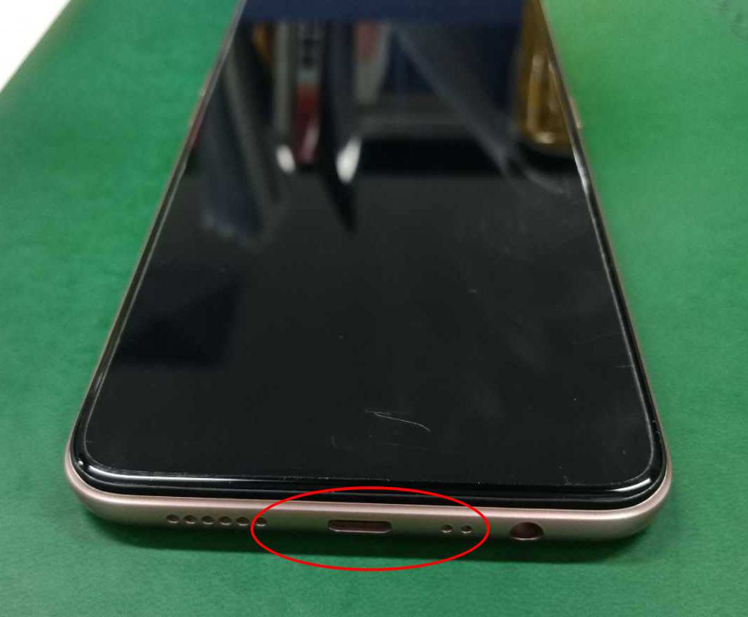
Figure 3-15
3) Hold the top of the phone with one hand and the teardown rod wrapped with a dust-free cloth in the other hand, as shown in Figure 3-16.
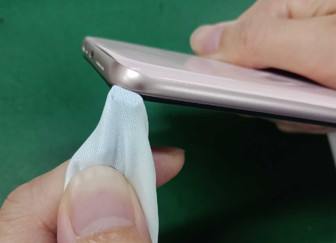
Figure 3-16
4) Start from a corner at the bottom of the phone, push hard to pry open the gap, and slide around the border until the back cover of the phone battery is easily removed. See figure 3-17.
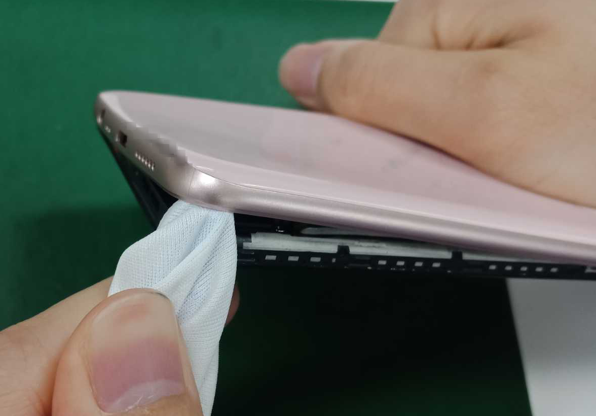
Figure 3-17
3.5 Anti-static plastic tweezers
3.5.1 Background
Metal tweezers and F-type special-tip plastic tweezers are sharp, which may puncture batteries or other devices during repair. Therefore, it is forbidden to use F-type special-tip plastic tweezers when repairing mobile phones. Metal tweezers can be used only in welding operations, in other cases, engineers should use flat head E-type plastic tweezers (tool code: 535267887), as shown in Figure 3-18.
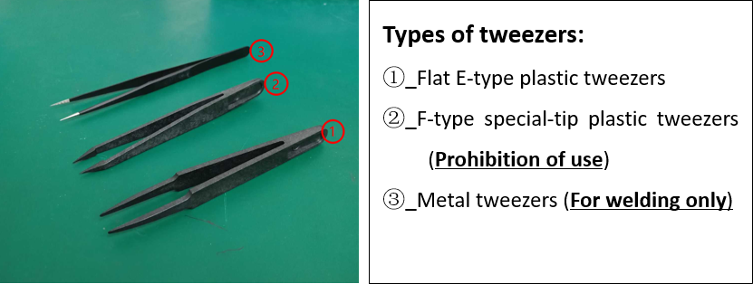
Figure 3-18 Tweezers
3.5.2 Involved scenes
E-type plastic tweezers are mainly used for: Remove the RF line, BTB holder, metal bracket, button FPC / motor FPC, clean the adhesive on the battery cover, etc.
3.5.3 Content
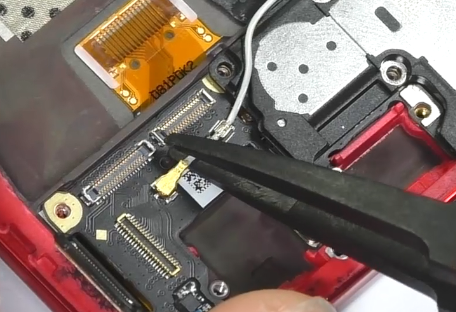
1. Remove RF line
Use E-type tweezers to reach the metal part of the bottom of the RF connector and gently lift it up, as shown in the figure below
2. Remove BTB seat
Use E-type tweezers to reach under the BTB seat, then gently pry it up.
3. Remove metal cover / metal bracket
For metal cover / brackets with snaps, use the tweezers to pry up the metal stand from the opposite side of the snaps. Pay attention to the direction of the snaps, otherwise it is easy to break the tweezers.
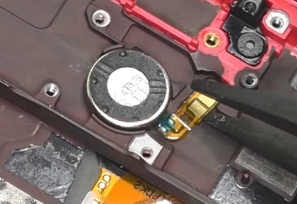
4. Key FPC / Vibration motor FPC
The key FPC / motor FPC is pasted with double sided adhesive, and the gap is small, you need to drip a few alcohol first. After the alcohol has penetrated into the double sided adhesive, making it weaker, use E-type tweezers to disassemble FPC.
5. Remove the double sided adhesive
Use plastic tweezers to grip the double sided adhesive, then slowly roll up the double sided adhesive in one direction, as shown in the figure below.
3.5.4 Cautions
The metal tweezers applied previously should be managed by each service center. If required, metal tweezers can be used for welding operations in some old models, it is prohibited to place the metal tweezers on the repair table to prevent puncturing the battery.
3.6 Key bracket disassembling tool
3.6.1 Background
The disassembling locations of key brackets for Reno2 is very narrow, which is difficult to disassemble. Service centers cannot find suitable tools to disassemble, engineers may use metal tweezers or other tools, so it could result in battery safety risks and damage the key brackets. Therefore, the factory will provide key bracket disassembling tools to help the engineers disassemble the key brackets easily.
3.6.2 Involved scenes
Reno2 and other module devices which have similar structure
3.6.3 Content
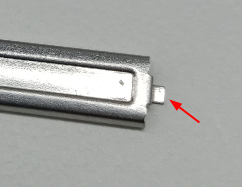
1. Key brackets disassembling tool (as shown in Figure 3-19, the material code: 3884060), volume key brackets (as shown in Figure 3-20)
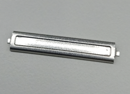
Figure 3-19 Key bracket disassembling tool
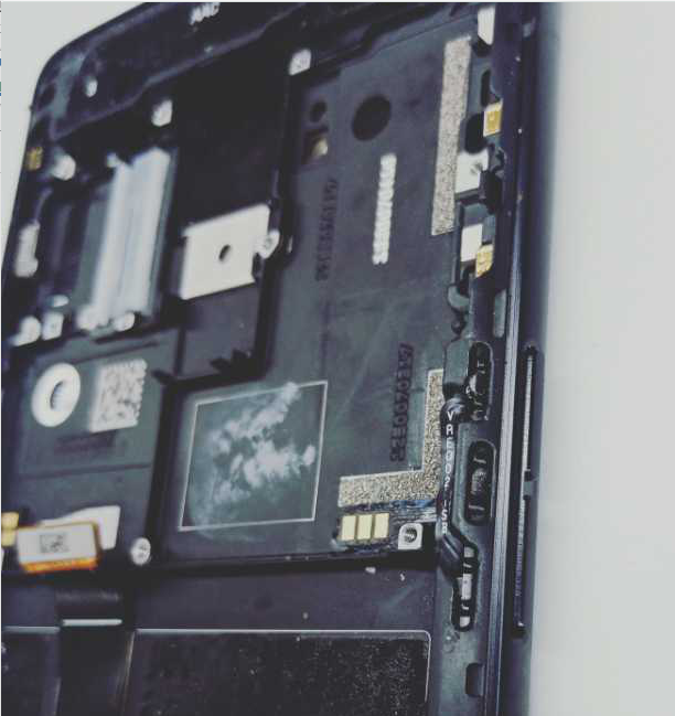
Figure 3-20 volume key brackets
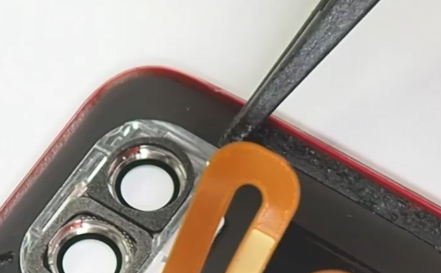
2. Plug any side of the convex bodies (as shown by the red arrow) into the disassembling locations of key brackets, and then disassemble them.
3. Press down the tool along the direction perpendicular to the screen, then pry up the side button brackets lightly (as shown in Figure 3-21). Do it in the same way for the power key brackets.
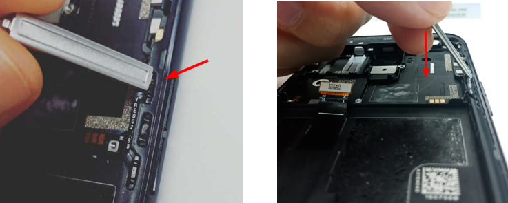
Figure 3-21 Direction for disassembly
3.7 Battery cover pressing fixture
3.7.1 Background
The battery covers of R15, R15 Dream Mirror Edition and later models are glued with double sided adhesive. Every time we open the battery cover to repair and replace with new double-sided adhesive. Battery cover pressing fixture is used to stimulate the adhesiveness of double-sided adhesive.
3.7.2 Involved scenes
The models whose battery covers are glued with double sided adhesive.
3.7.3 Content
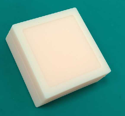
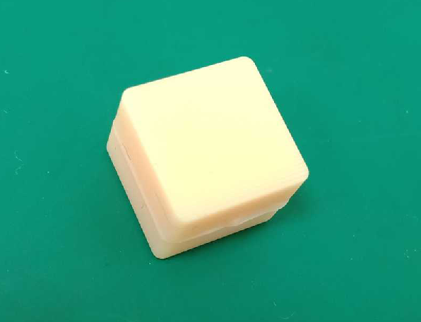
1. Battery cover pressing fixture consists of upper mold (tool code: 535621455) and lower mold (535621456), as shown in Figure3-22 and 3-23.
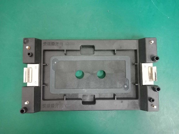
Figure 3-22 upper mold
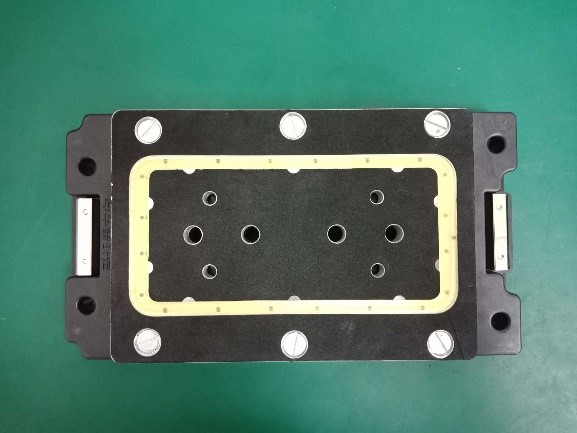
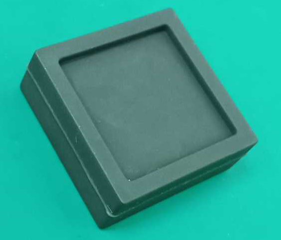
Figure 3-23 lower mold
2. The phone is placed according to the direction shown in Figure 3-24, and the direction of the receiver is consistent with the direction indicated by the fixture.
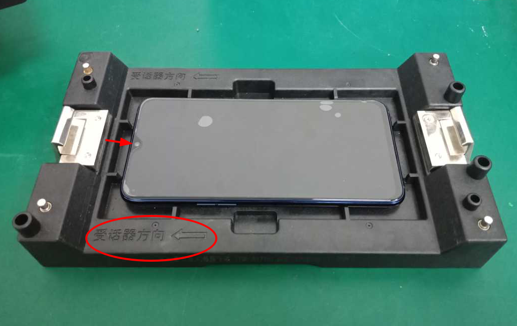
Figure 3-24
3. Position according to the two positioning posts, as shown in Figure 3-25.
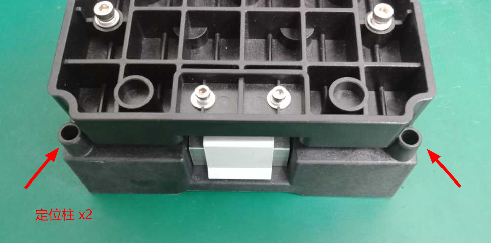
Figure 3-25
4. Then use both hands to slowly press down on both ends at the same time, as shown in Figure 3-26.
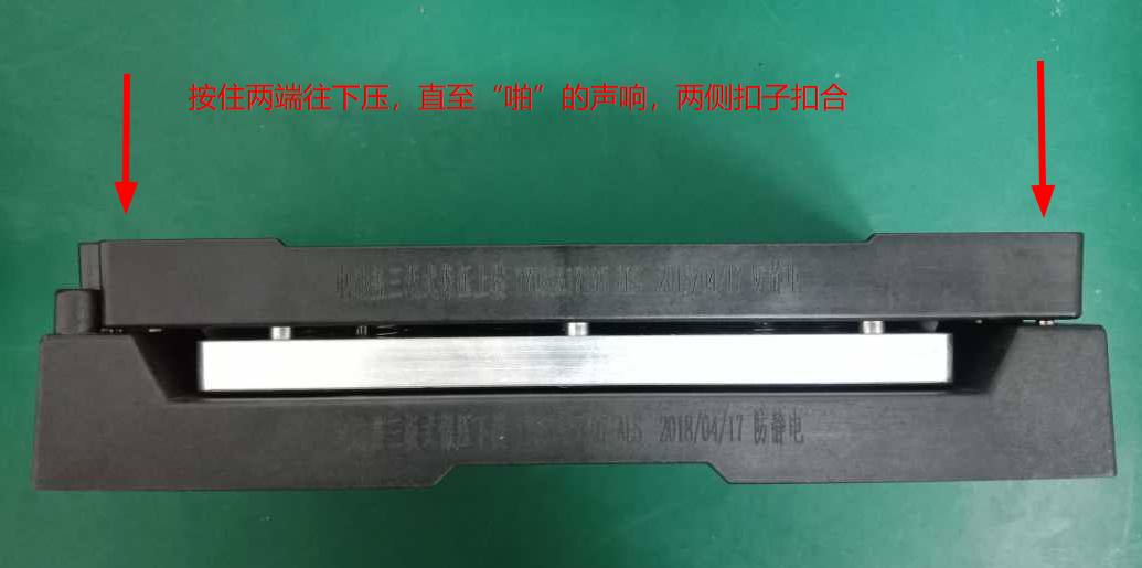
Figure 3-26
5. Hold for 7-10 minutes after fastening, as shown in Figure 3-27.
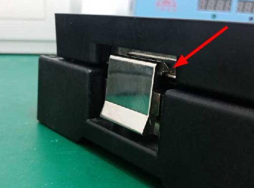
Figure 3-27
4. Cleaning tools
The place such as handset, headphone jack, USB port can be stained with dust. If the dirt is not cleaned for a long time, it will cause connection issue, which will accelerate the aging and depreciation, therefore it’s important to clean the handset regularly. Next, we are going to introduce several cleaning tools to remove dust and foreign objects.
4.1 Anti-static brush
4.1.1 Background
To better repair and clean the phones that enters liquid and dust, reduce the risk of damage to electronic components caused by electrostatic discharge. When using the brush in the customer service center, please refer to this guide strictly.
4.1.2 Involved scenes
Applicable to all the maintenance scenarios in customer service centers. For example: cleaning the corroded and oxidized mainboard, cleaning the dust that is into the receiver plugging holes, side keys, speakers, dirty on the surface of phones, etc.
4.1.3 Content
1. The third generation anti-static brush (material code: 535155093) is shown in Figure 4-1.
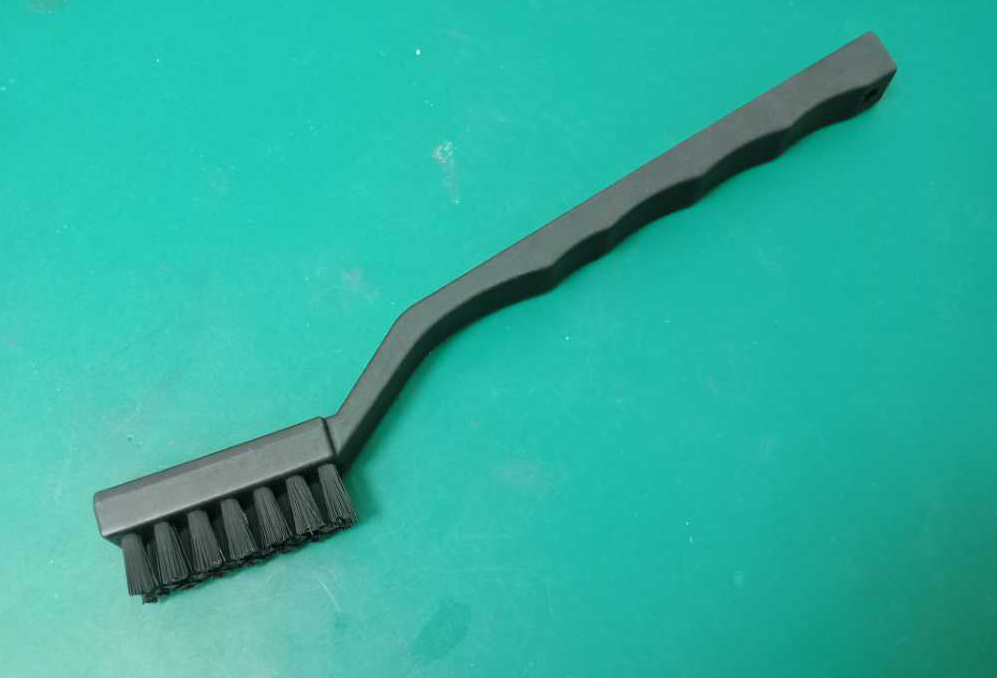
Figure 4-1
2. The hair diameter of the first and second generation anti-static brushes is 0.5mm, which are not allowed to use in service centers. The hair diameter of the third generation anti-static brush is 0.15mm, as shown in Figure 4-2.
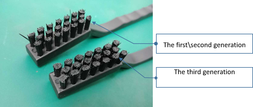
3. Only the third-generation anti-static brushes uniformly distributed by the company are currently allowed to use in service centers. The first and second generation anti-static brushes and ordinary toothbrushes (as shown in Figure 4-3) that were previously applied are prohibited to use in repair.
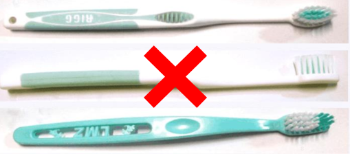
Figure 4-3
Note: This document will be implemented from the date of publication and added to the technical specialization assessment item.
5. Detection tools
5.1 Digital multimeter
5.1.1 Background
In repair, digital multimeter (tool code: 5380200007) can be used to detect the voltage, current, resistance, etc. in the circuit, to assist maintenance personnel to accurately judge the failure of the machine, thereby improving the efficiency of maintenance. In addition, when installing static and protective ground circuits, you can detect whether they are accurately grounded.
5.1.2 Involved scenes
Mainly used to measure voltage, current, resistance, and grounding test.
5.1.3 Content
1. Detect the resistance of anti-static wrist strap (Resistance standard: 0.8MΩ ~ 1.2MΩ)
1) Turn the multimeter rotary switch to the “Ω” position, as shown in Figure 5-1.
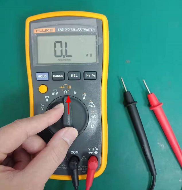
Figure 5-1
2) Hold the black pen with the alligator clip of the grounding end of the anti-static wrist strap, and the red pen touches the metal area, as shown in Figure 5-2. Under normal circumstances, the resistance of the anti-static wrist strap is about 1MΩ.
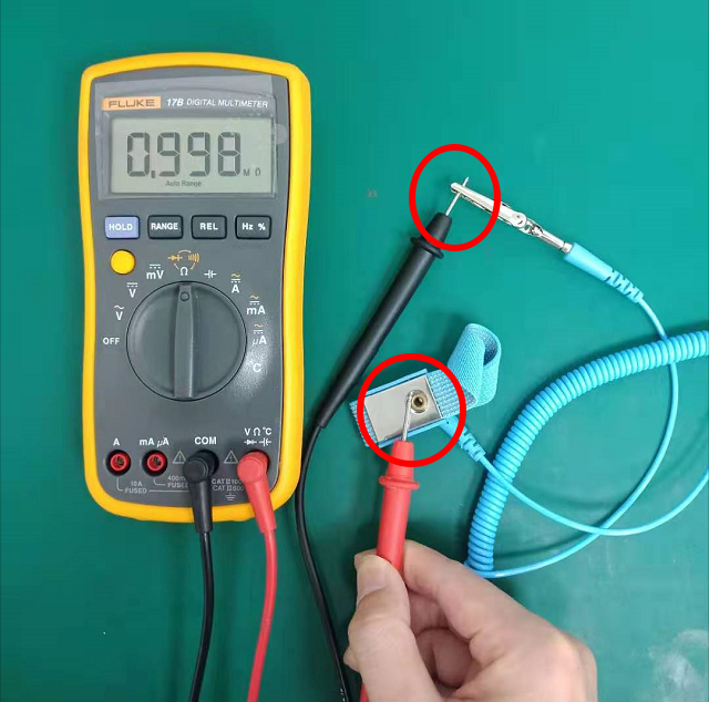
Figure 5-2
2. Detect the resistance of ground wire for maintenance workbench (resistance standard: 0.8MΩ ~ 1.2MΩ)
Hold the black pen with the alligator clip of the grounding end of the anti-static wrist strap, and the red pen touches the metal area, as shown in Figure 5-3. the resistance of the should be about 1MΩ.
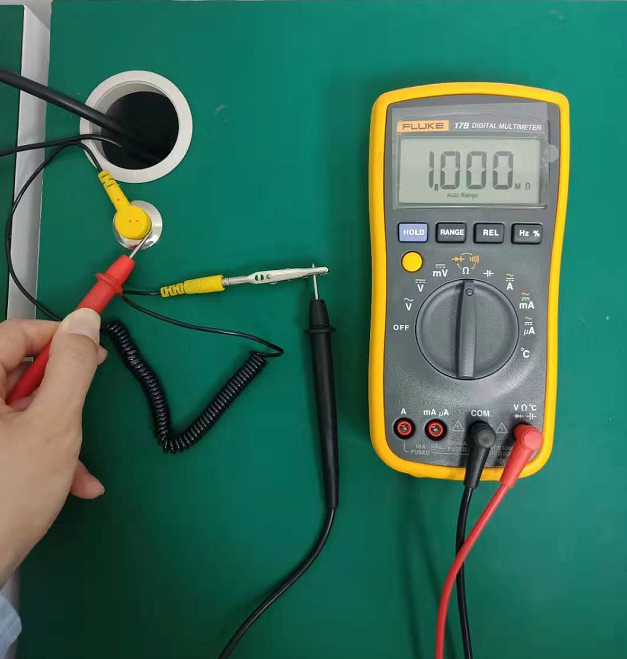
Figure 5-3
3. Grounding detection of ground wire of main power supply
1) Turn the rotating switch of the multimeter to the ac voltage gear.
2) This method is used to check whether the live, neutral and ground wires of the power supply are reversed, connected incorrectly and missed. The test steps are shown in Figure 5-4. The test voltage shown by the multimeter is qualified if it meets the following requirements.
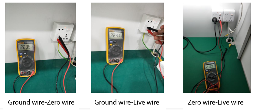
Ground Detection Voltage Reference Standard:
- Zero wire-Live wire (X): X= mains voltage
- Ground wire-Live wire (Y): Y= mains voltage ± 20V
- Ground wire-Zero wire (Z): 0.1V <Z< 20V
5.1.4 Cautions
1) When detecting the live-zero wire voltage of the power supply, the mains voltage standard is different in different regions (such as the national standard mains voltage is 220V in China), therefore, the test results displayed should reference on the local mains voltage standards.
2) If the resistance of anti-static wrist strap and ground wire for maintenance workbench is not between 0.8 MΩ and 1.2MΩ. Please replace with a new anti-static wrist strap or ground wire of maintenance workbench immediately.
5.2 DC Power Supply
5.2.1 Background
DC power supply (code: 5380180033) mainly plays two roles in repairs: 1) Simulating a normal charger; 2) Simulating a lithium battery to power the mainboard, which is used to check whether the working current value of the mainboard circuit is normal, whether there is a short circuit caused by excessive current, whether there is a large current or leakage current during standby. The setting method is different depending on the usage scenario.
5.2.2 Involved scenes
Test the current in the circuit to determine whether the mainboard or battery is normal.
5.2.3 Content
1. Simulating a lithium battery to power the mainboard (use with BTB test line)
1) When directly connected to the mainboard through the BTB test line, the channel output voltage must not be higher than 4.5V. Please lock the output voltage of the DC power supply first before connecting to the mainboard or phone. Select the corresponding channel (such as CH1, CH2) and set the voltage value to 4.5V (the green font shows the voltage value). After setting the output voltage, press the "LOCK" button (as shown in Figure 5-5) to lock the output voltage of the channel (the default factory voltage has been set to a maximum of 4.5V). Select the corresponding BTB test line according to the battery, as shown in Figure 5-5.1.
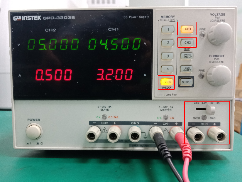
Figure 5-5
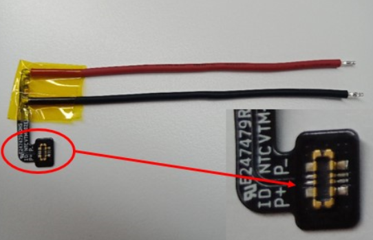
Figure 5-5.1 BTB test line
2. Connect both ends of the positive and negative wires of the BTB test line to the corresponding positive and negative wires of the DC power supply (at the red clamp and the black clamp), as shown in Figure 5-6. When trying to connect the mainboard, if the voltage is displayed as 1-2V and the current is displayed as the maximum value, which means a short circuit. At this time disconnect the power immediately, and then connect P +, P- reversely
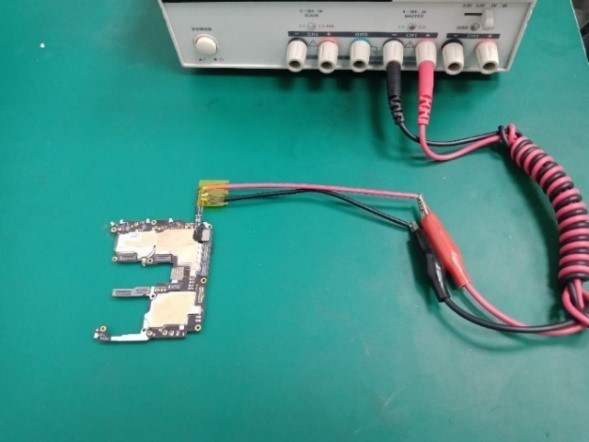
Figure 5-6
2. Simulating a normal charger
Cut the USB port of the data cable, and peel off the cable. There are red, black (or silver), white, and green cables, as shown in Figure 5-7. Connect the red and black (silver) wires of the USB to the corresponding color output ports of the DC power supply. Then connect the white and green wires each other, as shown in Figure 5-8. As the CH3 channel of GPD-3303S only has three positions of 2.5V, 3.3V and 5V, so we can lock it directly at 5V, which is only applicable to mobile phone charging test via USB cable.
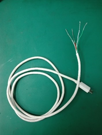
Figure 5-7
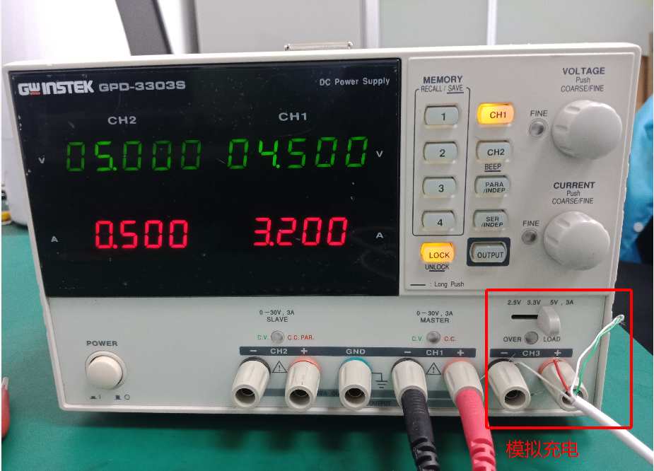
Figure 5-8
5.3 Temperature gun
5.3.1 Background
The customer service centers often encounter the problems that the users feedback the overheating of the mobile phones, and it is difficult for the repair engineers to confirm whether the feedbacks is normal. Therefore, the company will provide temperature guns (tool code: 5350000032) for the customer service centers, assisting maintenance engineers to determine the heating problem more intuitively and accurately.
5.3.2 Involved scenes
Measuring the heat near the receiver/near the camera/on the display surface/in the upper part of the back cover of the battery
5.3.3 Content
1. Introduction to temperature gun
The temperature gun is used to measure the surface temperature of the object. Its light sensor radiates, reflects and transmits energy, and then the energy is collected and focused by the probe, and then other circuits convert the information into readings and display it on the machine.
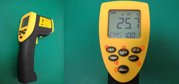
Figure 5-9
Emissivity adjustment method: After booting, press the ”FUNC” key until the icon "EMS" appears on the bottom line and blinks. Press the UP or DOWN key to adjust the emissivity (range: 0. 01-1.00), press the SET key to confirm. After “EMS” stop flashing, it can be measured according to the adjusted emissivity.
Most organic and paint or oxidized materials have an emissivity of 0.95, which is the default adjustment of machine.
2. Measuring standards
1) According to the user's actual heating situation description, reproduce the heating scene in a non-charged environment.
2) Use the temperature gun to align the hot spot (where the user describes the hot spot), then read the temperature value on the display of the temperature gun, repeat this operation three times, and take the highest value as the final result.
3) Compare the results with the standard temperatures for the corresponding cases in the table below. If the heat situation reported by the user belongs to a mixed scene, take the highest standard value in the scene as a reference.
Specific test reference standards please refer to the table below:
|
Scenes |
Test positions |
non-charged environment |
|
Call |
Around the receiver |
≤37°C(102°F) |
|
Video / photo |
Around the camera |
≤47°C(117°F) |
|
Video call (WeChat) |
Screen surface; upper half of battery back cover |
≤47°C(117°F) |
|
Watching video(Wi-Fi) |
Screen surface; upper half of battery back cover |
≤45°C(117°F) |
|
Playing games |
Screen surface; upper half of battery back cover |
≤47°C(117°F) |
|
Charging |
Screen surface; upper half of battery back cover |
≤40℃(adapter≤20W) |
Reference Standards
4) Measuring the following main areas, as shown in the red area in Figure 5-10.

Figure 5-10
5.3.4 Cautions
1. At room temperature of 25±0.5℃, without charging, tear off all protective film before test.
2. Restart the phone or clear the background apps, then turn off all switches (such as automatic brightness adjustment / Bluetooth / positioning, etc.).
3. The emissivity is set to 0.95. For the above scenarios, the temperature must be below 28 ° C before testing each side of the phone. And the temperature test can be performed after 30 minutes.
5.4 NFC card reader
5.4.1 Background
Some current models have gradually added NFC function. After disassembling and repairing, this function needs to be tested, making sure NFC module is normal.
5.4.2 Involved scenes
Use for NFC test
5.4.3 Content
1. NFC card reader (code: 535624316), as shown in Figure 5-11
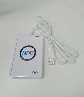
Figure 5-11

Figure 5-12
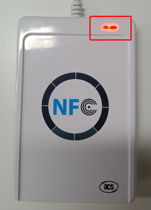
Figure 5-13
2. The test steps are as follows:
1) Connect the NFC card reader to the computer's USB port. The computer will automatically install the driver. After the installation is successful, the computer will display as shown in Figure 5-12. Then the red light of the NFC card reader will stay on, as shown in Figure 5-13.
2) Enter "* # 899 #" on the dial interface > automatic testing > NFC test. The phone will automatically check SIM 1 simulation by default, indicating that it is ready to be used as a card, and the NFC switch will be automatically turned on at this time.
3) Move the camera area of the mobile phone closer to the card reader, then the NFC card reader indicator will change from red to green with a beep sound, meaning it passes the test, as shown in Figure 5-14.
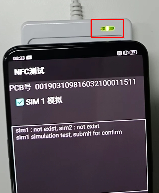
Figure 5-14
5.5 8V boost fixture
5.5.1 Background
It needs around 8V to normally power the mainboards of The Find X Super VOOC and Lamborghini editions. However, the output voltage of the DC power supply used by the customer service centers is fixed at a maximum of 4.5V. Therefore, a special boost fixture is required to raise the voltage from 4.5V to 8V to meet the requirements of the mainboard power supply test. In the future, the models of Super VOOC can use this boost fixture.
5.5.2 Involved scenes
SUPER VOOC models can use this boost fixture, such as Find X Super VOOC \Find X Lamborghini edition \ R17 Pro \ Reno ACE
5.5.3 Content
1. Introduction to 8V boost fixture (code: 535355301), as shown in Figure 5-15 and 5-16
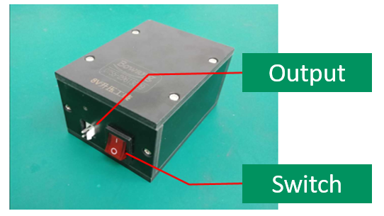
Figure 5-15
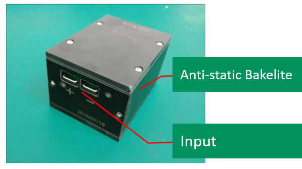
Figure 5-16
2. Introduction of 8V BTB test line (code: 535165703), as shown in Figure 5-17
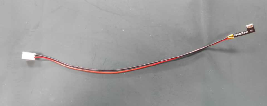
Figure 5-17
3. Steps
1) Connecting the output of the DC regulated power supply to the input of the boost fixture. The positive pole (+) of the fixture input corresponds to the positive pole (+) of the DC power supply, and the negative pole (-) corresponds to the negative pole (-), as shown in Figure 5-18.、
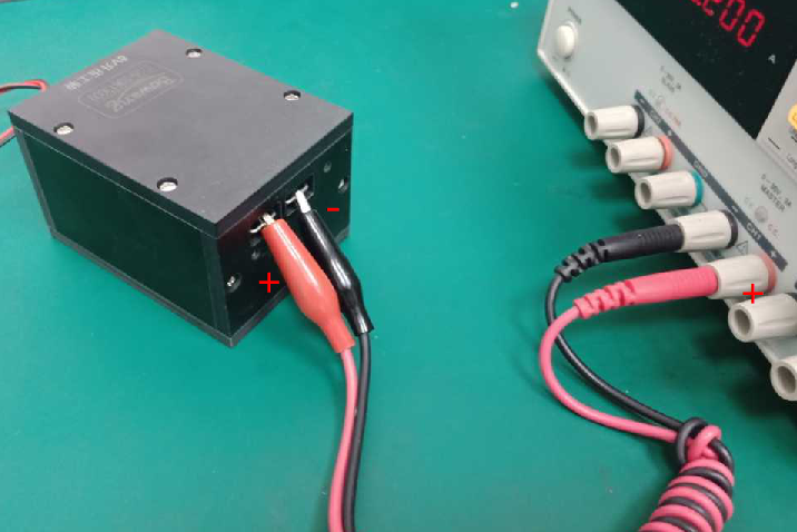
Figure 5-18
2) Connecting the 8V battery BTB test line to the voltage output of the 8V boost fixture. It can provide 8V power voltage for the mainboard, as shown in Figure 5-19.
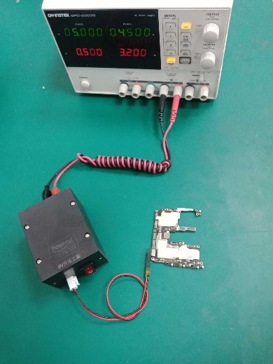
Figure 5-19
5.6 Optical fingerprint calibration fixture
5.6.1 Background
The optical fingerprint module of the new models is upgraded, and the old fingerprint calibration fixture available in the customer service centers cannot be used for the new models. For fingerprint calibration, a new generation of optical fingerprint calibration fixture will be used, which will be compatible with the fingerprint calibration function of the previous generation.
5.6.2 Involved scenes
Use for calibrating those models that have optical fingerprint function
5.6.3 Content
1. Parts list
|
Item |
Name |
Material code |
QTY |
Unit |
Picture |
|
1 |
Flesh-colored silicone head (30*30*12) |
5353003576 |
1 |
pcs |
|
|
2 |
Black silicone head (30*30*12) |
5353003577 |
1 |
pcs |
|
|
3 |
Striped silicone head |
535191206 |
1 |
pcs |
|
|
4 |
Silicon head fixing tooling (600g) |
5353003674 |
1 |
pcs |
|
Parts list
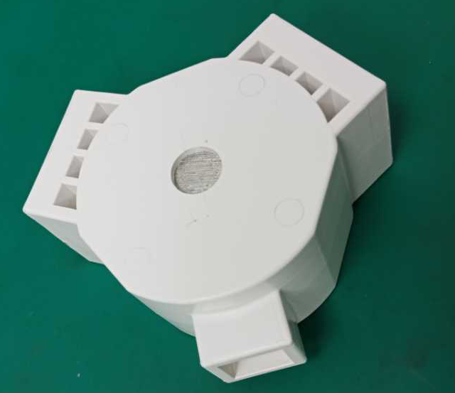
2. Installation tips
1) The silicone head (flesh-colored\black\) for fingerprint calibration is installed into the large slot of the fixed tooling with the groove facing towards, as shown in Figure 5-20 and Figure 5-21.
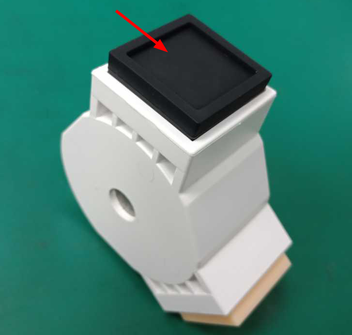
Figure 5-20
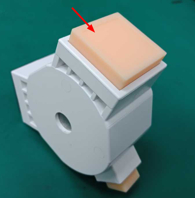
Figure 5-21
2) The silicone head (striped) for fingerprint calibration is installed into the large slot of the fixed tooling with the striped side facing towards, the installation direction of the striped silicone head is shown in the red line in Figure 5-22.
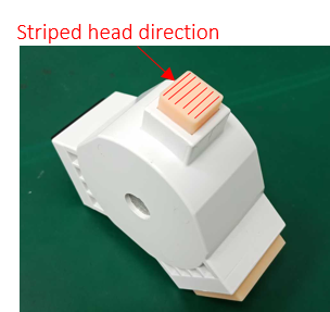
Figure 5-22
3. Calibration scenes
1) During repair, if the mainboard is replaced or the screen component/fingerprint module is replaced, the fingerprint must be recalibrated.
2) If the protective film is replaced or removed by our staff in the service center, the fingerprint must be recalibrated.
3) After the system is upgraded, the fingerprint must be recalibrated.
Note: You need to restart the phone after finishing the fingerprint calibration, then delete the previous fingerprint and re-enter it.
4. Calibration steps
1) Enter "* # 899 #" on the dial interface > After-sales device calibration > Enter the password "6776" in the input box, as shown in Figure 5-23.
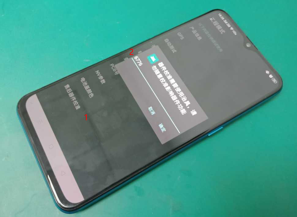
Figure 5-23
2) “Infrared calibration under the screen” test, just follow the instructions.
3) "Light leakage calibration" test, just follow the instructions.
4) “Fingerprint Optical Calibration” test. click “NEXT” to enter calibration. According to the "Place a flesh-colored rubber head" prompt, cover the fingerprint spot area with a flesh-colored silicone head. Then place and click "NEXT", remove the flesh-colored silicone head until the prompt "Please place the black silicone head" shows, as shown in Figure 5-24.
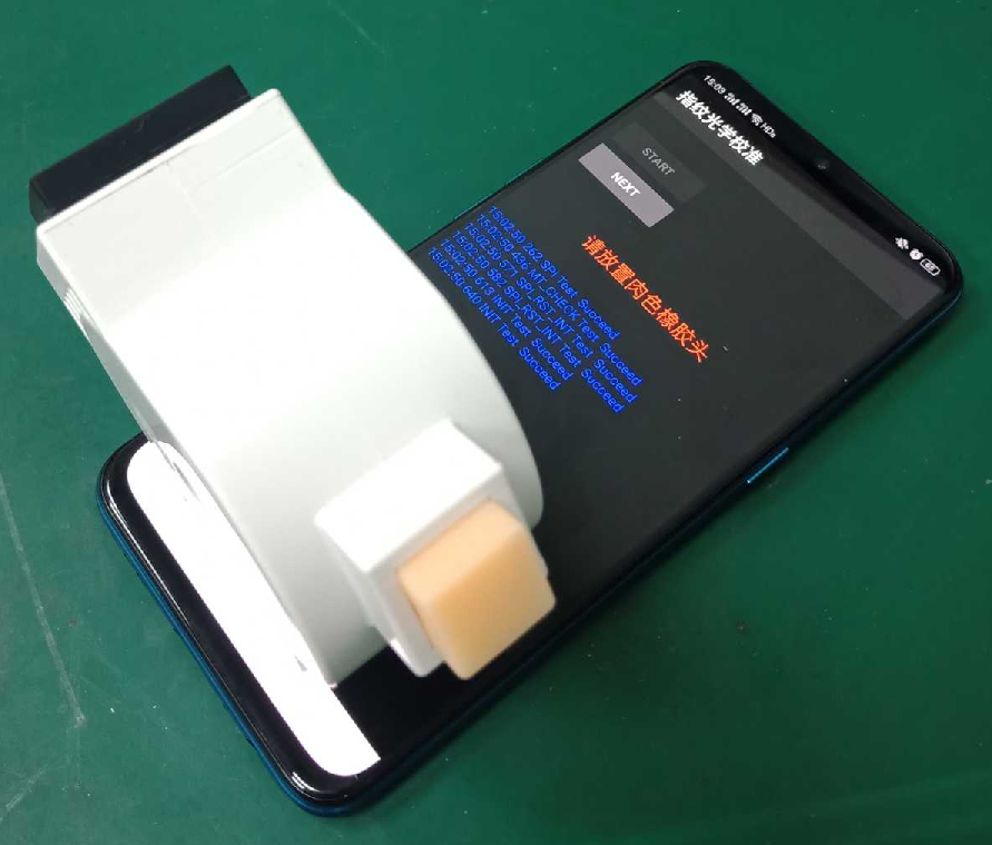
Figure 5-24
5) According to the "Place a black rubber head" prompt, cover the fingerprint spot area with a black silicone head, as shown in Figure 5-25. Then place and click "NEXT", remove the black silicone head until the prompt "Please place Chart card" or “Please place the striped rubber head” shows.
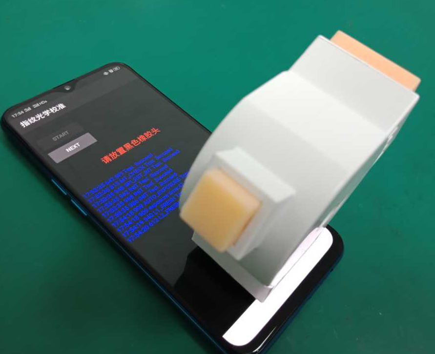
Figure 5-25
6) According to the "Place a striped rubber head" prompt, cover the fingerprint spot area with a striped silicone head, as shown in Figure 5-26. Then place and click "NEXT", remove the striped silicone head until the prompt "Please restart after the test” shows.
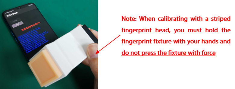
Figure 5-26
5.6.4 Cautions
1. The striped silicone head has a small area, which is easy to fall when placed vertically. You must hold the fixture by hands when you are calibrating it (please do not press the fixture with force) to prevent the fixture from being unstable and causing the screen to break.
2) During the calibration, when the silicone head is pressed on the fingerprint spot, no green fingerprint spot leakage is allowed.
3) Note that the installation direction of the striped silicon head is shown in the Figure 5-27 below.
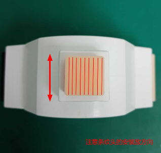
Figure 5-27
5.7 Camera Calibration Graph
5.7.1 Background
After replacing the mainboard, disassembly screen assembly, fingerprint module, after-sales calibration is required in service center. During the process, we need to use "Camera Calibration Graph" to complete "After-sales Calibration". The purpose is to match the rear dual cameras, otherwise it will affect the blur effect of portrait mode.
5.7.2 Involved scenes
AF+FF Dual Cameras
5.7.3 Content
1. Chart card (code: 535601861), as shown in Figure 5-28.
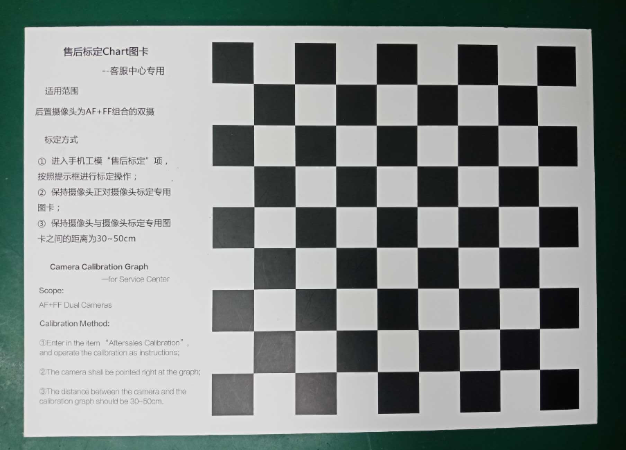
Figure 5-28
2. After entering in the item "After-sales Calibration", keep the camera facing the Camera Calibration Graph, and follow the instructions to align the yellow box with the black and white grid edges of the Graph (the distance between the camera and the Camera Calibration Graph is 30 ~ 50cm after alignment). Then click “taking photo”, as shown in Figure 5-29.
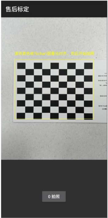
Figure 5-29
3. At this time, you will enter the calculation interface. Do not perform any operation during this time, as shown in Figure 5-30.
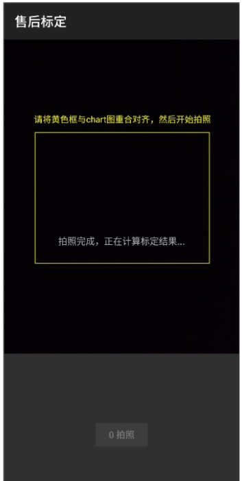
Figure 5-30
4. If the result shows “Fail”, adjust according to the prompts and re-calibrate until the calibration shows “Pass”, as shown in Figure 5-31.
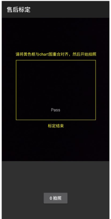
Figure 5-31
5.8 Plug gauge
5.8.1 Background
For the detection of deformation fault of the whole machine, at present, the staffs of some customer service centers use A4 paper for detection, which is easy to cause users to question, giving them the feeling that the measurement accuracy is low and not professional. Therefore, plug gauges (code: 535050024) are needed in service centers to detect whether mobile phones are deformed.
5.8.2 Involved scenes
Use for detection of deformation of the mobile phones or excessively large screen gaps.
5.8.3 Content
1. Deformation detection of mobile phone
1) For a mobile phone with obvious bending deformation, first place it on a flat workbench surface and perform preliminary tests with the naked eye, as shown in Figure 5-32, and then use the plug gauge for further testing and judgment;
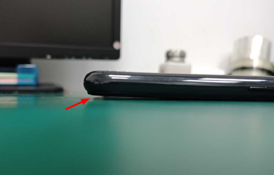
Figure 5-32
2) First remove the screen film, then place the phone on a flat workbench surface with the screen facing down, as shown in Figure 5-33;
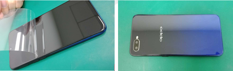
Figure 5-33
3) Select a 0.5mm plug gauge, as shown in Figure 5-34;
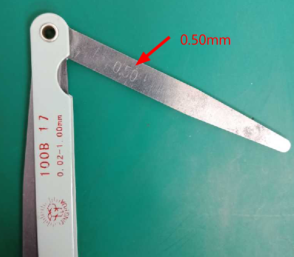
Figure 5-34
4) Keep the plug gauge parallel to the workbench surface, then insert into the upper / middle / lower sides of the phone, as shown in Figure 5-35. See if the plug gauge can insert into the gap and whether there is no friction during the insertion. If not, it means that the deformation of the phone is less than 0.5mm, the phone is a good product; otherwise the phone is an abnormal machine.
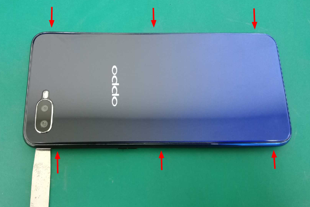
Figure 5-35
Note: As shown in figure 5-35, as long as the test result of one of the six detection locations does not meet the standard of 0.50mm, the mobile phone can be judged as an abnormal product.
2. Detecting excessively large screen gaps
1) Select a 0.15mm plug gauge, as shown in Figure 5-36;
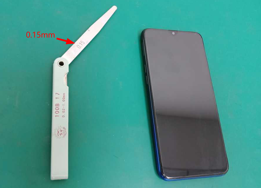
Figure 5-36
2) Insert the plug gauge into the gap perpendicular to the screen direction, and gently slide the plug gauge along the gap, as shown in Figure 5-37. See if the plug gauge can insert into the gap and whether there is no friction during the insertion. If not, it means that the deformation of the phone is less than 0.15mm, the phone is a good product; otherwise the phone is an abnormal machine.
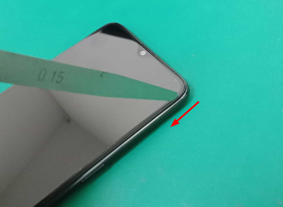
Figure 5-37
6. Welding tools
In the daily maintenance of the customer service centers, if it involves repairing mainboard, some welding tools such as hot air desoldering stations and lead-free soldering stations which are mainly used for welding of small components or chips of mobile phones. Therefore, engineers not only need to be proficient in the operation of soldering tools, but also need to master the disassembly and soldering methods of chips and components.
6.1 Hot air desoldering station
6.1.1 Background
Hot air desoldering station is one of the commonly used tools in welding. It is mainly used to weld and extract components by hot air blowing from the core of hot resistance wire gun. Hot air desoldering station are used for removing or soldering small components or integrated circuits.
6.1.2 Involved scenes
1. Removing or soldering small SMD components, such as SMD resistor, SMD inductor, SMD capacitor. For these small components, hot air desoldering station are generally used for blow welding.
2. Removing or soldering IC, The surface of the chip should be coated with appropriate amount of flux when blow it, so as to prevent dry blowing, and can melt the solder of the chip.
3. Dry the components with a hot air.
6.1.3 Content
1. Product description
Hot air desoldering station (code: 535480069), as shown in Figure 6-1:
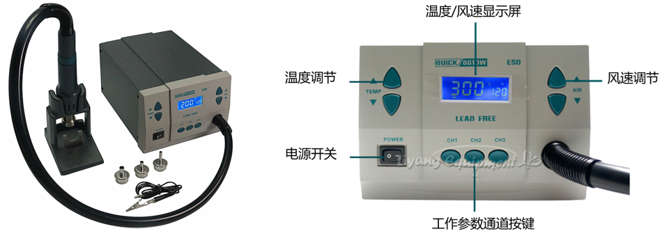
Figure 6-1
2. Remove the shielding case
Setting the temperature of the hot air desoldering station to about 360°C, and the wind speed is moderate. A small nozzle is generally used to remove the shielding case. After the temperature and airflow are stable, you can use a hot air desoldering station to remove the shielding case with metal tweezers, as shown in Figure 6-2.
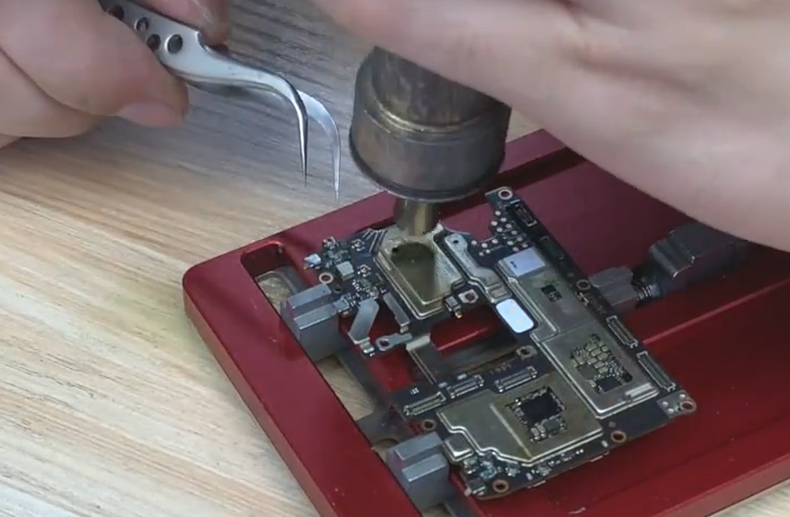
Figure 6-2
3. Desoldering SMD Components
SMD components in mobile phones mainly include SMD capacitors, SMD inductors, and SMD transistors. A small nozzle are generally used to remove and weld small SDM component, the hot air temperature is set to about 360°C, the distance between nozzle of the hot air desoldering station and the parts to be removed is 2 ~ 3cm. Heat evenly over the component until the solder around the component melts, then remove it with metal tweezers. Be careful not to pry the components hard, so as not to damage the pads, as shown in Figure 6-3.
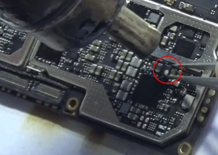
Figure 6-3
4. Desoldering CPU or IC chips
Large nozzles are usually used to desoldering chips, and the hot air temperature is about 360 ° C. Keeping the distance between the nozzle of the hot air desoldering station and the chips to 2~3cm, and heat evenly over surface of the chips, as shown in figure 6-4.
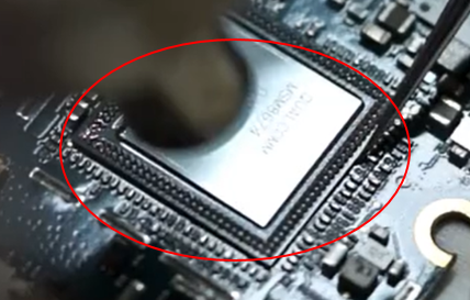
Figure 6-4
4. Blow-dry moisture on the surface of the internal components
First, disassembly the phone, then blow-dry the moisture with a hot air gun. The temperature of the hot air gun is set to 100 ± 20 ° C. During the drying process, be careful not to blow on the component all the time, so as to avoid further damage to the components.
6.2 Lead-free soldering station
6.2.1 Background
Lead-free soldering stations are most commonly used for PCB circuit board soldering in electronics factories, especially lead-free precision electronic.
In order to meet the requirements of the precision electronic processing industry, lead-free soldering stations are generally required to have a temperature lock function, and there must be no large deviations. It should have anti-static function, the welding process for the precision chip needs strict anti-static requirements.
6.2.2 Involved scenes
SMD component welding, motor replacement, USB charging interface replacement, etc.
6.2.3 Content
1. Product description
Intelligent lead-free soldering station (code: 535235099), as shown in Figure 6-5
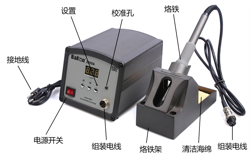
Figure 6-5
2. Removing the chip with a hot air gun, the temperature of the lead-free soldering station is controlled at about 360°C, then cleaning the solder residue on the pad and the chip with a soldering tape and a soldering iron, the steps are shown in Figure 6-6
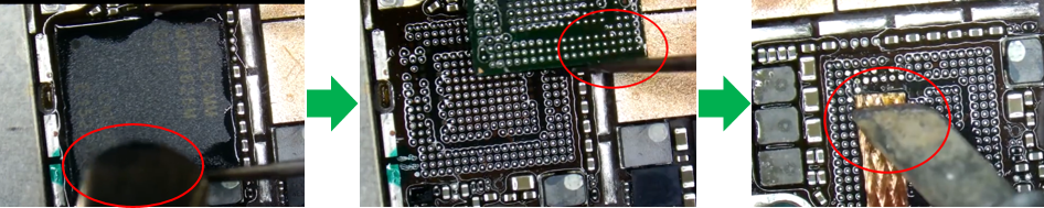
Figure 6-6
3. Replacing the USB charging interface.
The USB charging interface of the old models is loose or damaged. You can use a soldering station or a hot air gun to replace the charging interface. The steps are shown in Figure 6-7.
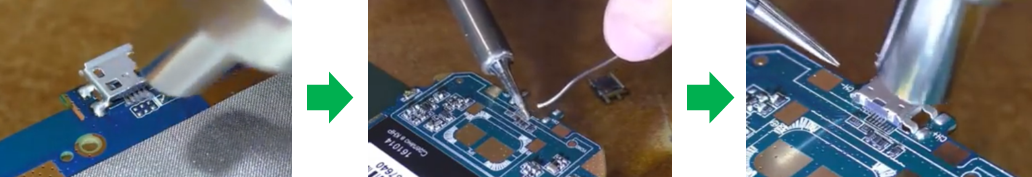
Figure 6-7
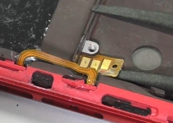
4. Replacing motors.
The motors of earlier mobile phones were welded to the board by two wires. If the motor is abnormal, it must be replaced, as shown in Figure 6-8.
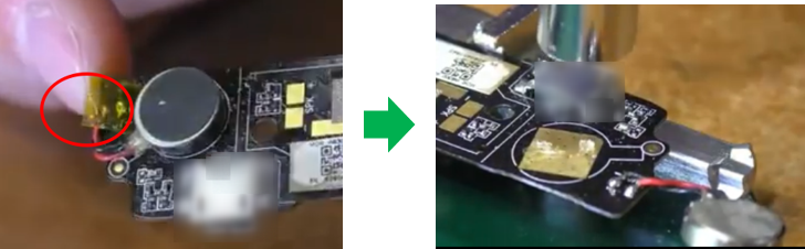
Figure 6-8
7. Other tools
7.1 Handheld barcode scanner
7.1.1 Background
In order to improve the accuracy of mobile phone software version input and help staffs of customer service centers to record information more quickly and accurately. Therefore, handheld barcode scanners or QR code scanner are necessary. Starting from model R9s, the mobile phone software version information has been integrated into the QR code. You can enter the * # 899 # in the dial-up interface of the mobile phone, then the QR code will pop up. Then scan the QR code with the handheld barcode scanners on the system, which will automatically bring out the IMEI code, software version and other information.
7.1.2 Involved scenes
Scanning the QR code of products, then acquiring the IMEI code, software version, material code of components and other information.
7.1.3 Content
1. For new models, the staffs must scan all QR codes and record related information into the system (except those models that are not turned on).
1) Enter * # 899 # on the dial interface of the mobile phone, then the related QR code of the product information will pop up, as shown in Figure 7-1

Figure 7-1
2) On the system's recording interface, click the blank of the “Product Bar Code” column(as shown in Figure 7-2), and then point the code scanner at the QR code, then click to scan, and the IMEI and software version information will be displayed automatically.
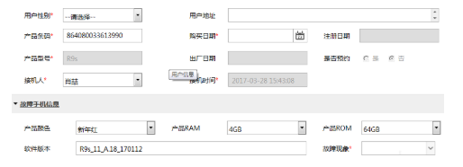
Figure 7-2
2. Scan the QR code of the adapter and battery
When the failure reason is “Battery bad” or “Battery charger bad”, you need to enter the SN number (the attachment SN is required at this time). You can use a handheld barcode scanner to scan the QR codes of the battery or adapter, the SN will be automatically filled in the blank, as shown in Figure 7-3.
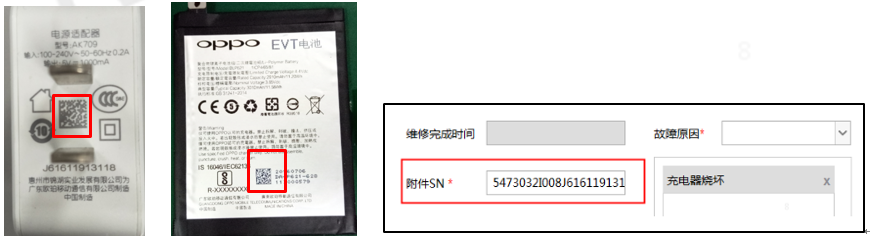
Figure 7-3
3. Scan the QR code of mainboard
The QR code on the mainboard is small, you need to place the scanner at a distance of 4~5 cm from the mainboard, and then aim the red beam at the front of the QR code to scan, as shown in Figure 7-4
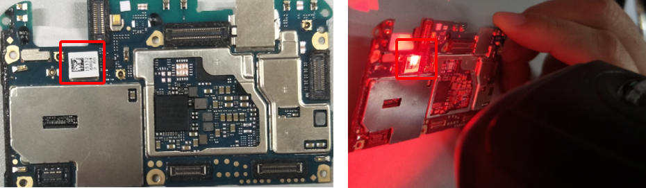
Figure 7-4