R17 Neo&RX17 Neo&AX7 Pro Service Manual V1
Views: 0 • Likes: 0
1.Guidance
The purpose of this document is to help OPPO levels 1 and 2 maintenance technicians to carry out service to OPPO products. This Service Manual is to be used only by authorized OPPO maintenance service centers, and the content is confidential. Please note that OPPO provides also other guidance documents (e.g. Technical Service Bulletins) for maintenance service cooperative corporations, therefore, please follow the guidance regularly and comply with the given instructions. While every endeavor has been made to ensure the accuracy of this document, some errors may exist. Please keep in mind also that this documentation is continuously being updated and modified, please keep watching out for the newest version.
1.1 Warnings and Cautions
Please refer to the handset's user guide for instructions relating to operation, service and maintenance including important safety information. Note also the following:
Warnings:
1)Service centers may be required to install the handset's vehicle-mounted system in vehicles. Under certain fault conditions, the handset's RF signals may affect the operation of the vehicles' electric power management systems and anti–skid braking systems (ABSs). If necessary, consult the vehicle dealer/manufacturer to determine the immunity of vehicle electronic systems to RF energy.
2) The handset must not be operated in areas likely to contain potentially explosive atmospheres, such as petrol stations, gas stations and blasting areas.
3) Operation of any radio transmitting equipment, including handsets, may interfere with the functionality of the medical devices protected by industrial mechanisms. Consult the manufacturer of the medical device if necessary. Other electronic equipment may also be subject to interference.
1.2 Attention
1) Maintenance and calibration must be undertaken by qualified technicians only.
2) Ensure all work is carried out at an anti-static workstation and that an anti-static wrist strap is worn.
3) Use only approved materials as specified in the bill of materials (BOM) list.
4) Ensure all components, screws and insulators are correctly re-fitted after maintenance and calibration. Ensure all cables and wires are repositioned correctly.
Electrostatic discharge can easily damage the sensitive components of electronic products. Therefore, every service center has to take care of OPPO's ESD protection requirements. Also see ESD Protection Requirements in this Service Manual
2. General Repair Information
※In this section the technician will get some general hints to carry out repairs:
Customer service personnel can download and read product documentation on:Download and read the product guide or user manual.
Before starting the repair, you must enter the ESD Protected Area and connect your wristband. Use gloves to avoid corrosion and fingerprints. Protect windows and display screens with a film to avoid dust and scratches. When cleaning the metal pads, you have to use a soft cloth/ESD brush and isopropanol. It is not allowed to use an eraser because it scratches the surface and will lead later on to oxidation and corrosion. Mechanical parts (except shielding covers and bent parts), which cannot be repaired in the event of a failure, can only be replaced, if they are not soldered. After removing and maintaining the shielding covers, make sure to replace them with new ones. Otherwise, the high-frequency leakage can have an influence on the device. Always use original OPPO spare parts. Check the soldering joints of the parts, which are concerned regarding the indicated error (e.g. soldered connectors or switches) and re-solder them if necessary (only repair centers that can conduct lead-free soldering). Remove redundant soldering flux after soldering. Assemble the handset with the standard screw torque (see the Introduction of the Service Manual).
Always use your own equipment for testing where you are sure that it works. For complaints about charger function, please test the handset with your own charger to be sure if the handset or charger causes the malfunction. When doing the fault log entries, always note the fault code which caused the malfunction. The accuracy of this code will be a great help to quality improvement. (Please refer to the relevant files if necessary).
Many service documents are available on the FTP server: ftp://wxfuwu@172. 16. 103. 212:919.
3.Overview
3.1 Purpose
The manual mainly introduces the disassembly and assembly method of 18311 and derived models to guide aftersales to repair phones correctly and avoid unnecessary waste.
3.2 Overview Introduction to the Assembly
Schematic diagram of whole machine
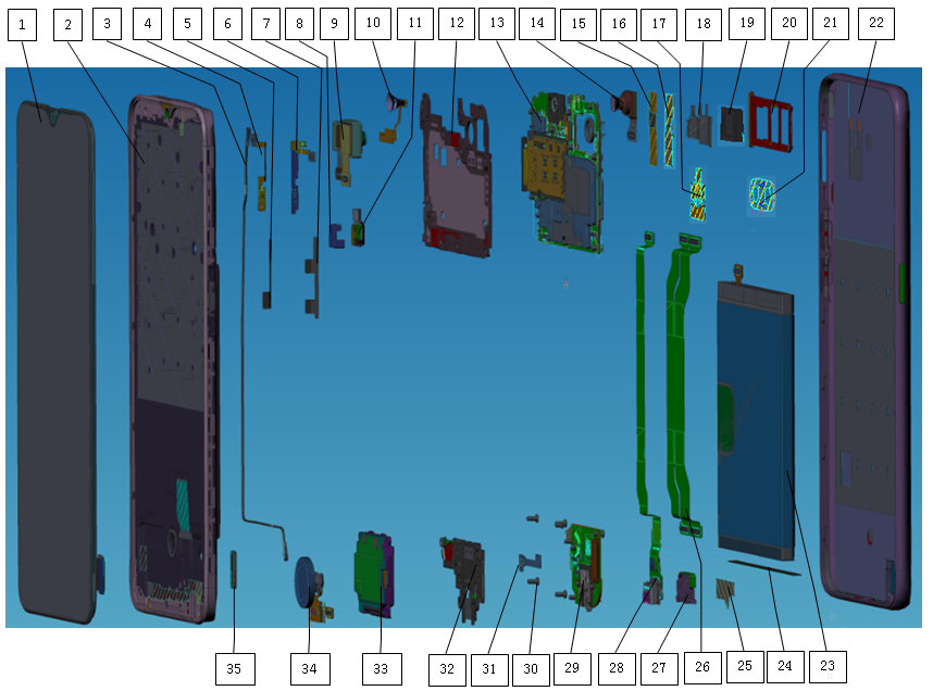
3.3 Corresponding Relationship BOM
Note:only for the annotation parts, not suitable for materials preparation, preparation materials please refer to the project IE or factory customer service department published "after-sales requirements of materials and supporting materials correspondence table"
3.4 Material code and picture
5. Disassembly procedure
(10)All Machine Materials after disassembly:
All parts of the machine as shown below: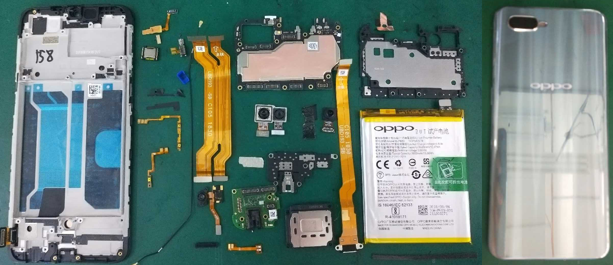
6. General precautions
(1) All accessories, including double-sided adhesive, graphite sheet, copper foil, conductive cloth, foam, once disassembled, cannot be reused;
(2) All the appearance of pieces must be checked after removal;
(3) All electronic components must be tested after the functions are tested;
(4) Disassembling parts must be marked with the assembly mark according to the general specification: defective products make bad identification distinction, so as not to mix;
7. Assembly Procedure
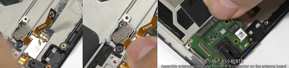
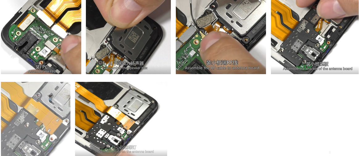
7.1. Take the upper cover assembly and power key FPC, assemble the power key FPC to upper cover assembly, and assemble the volume key FPC(Pay attention not to paste the volume key on the upper side wall, and assemble it after the RF cable is installed.); Then assemble the light sensor and receiver (Pay attention to the direction of the receiver's shrapnel );assemble the motor Silicone Case to motor , and then assemble the motor to the upper cover assembly; 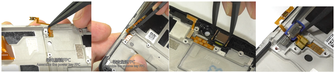 7.2 Assemble the fingerprint FPC on the top cover assembly , assemble 2 pcs screws to fix fingerprint, and then install the antenna board into the motherboard cover from the left side (Pay attention to the buckle); Install the display BTB & fingerprint BTB & main FPC BTB to antenna board; install the speaker box bracket to the motherboard cover, take RF cable, fasten it to the antenna board, and then smooth the RF into the cable slot; Assemble the antenna bracket , then assemble the USB FPC, and install 9 pcs screws to fasten the antenna bracket ;
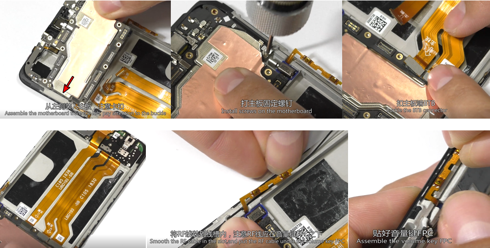
 7.3 Put the motherboard into the cover of the motherboard and insert from the left side obliquely (Be careful of the lock position). Install the motherboard screws, buckle the display FPC BTB and USB FPC BTB on the motherboard, and paste the FPC on the upper cover assembly without lifting; Fasten and smooth the RF line of the motherboard(pay attention to the RF cable under the volume key FPC);
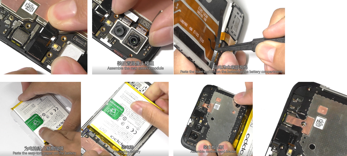
7.4. Put the front camera into the motherboard, and buckle the front camera BTB,paste the front camera Graphite sheet, then put the rear camera into the motherboard, and buckle the rear camera BTB(avoid the handle contacting camera lens); Paste the bottom of the battery compartment with the foam, and paste the easy-tore paper on the battery(pay attention make it flat), assemble the battery after making sure that there is no foreign matter on the battery compartment and the FPC is pasted flatly , then assemble the Battery BTB to motherboard . Assemble the motherboard bracket , paste the receiver copper foil, and then install 10 PCS screws to fix the motherboard bracket .
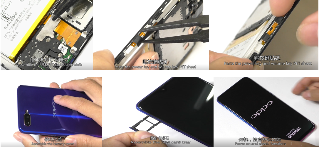
 7.5. Paste the USB plate conductive cloth, the power button PET sticker and the volume key PET sticker; then assemble the battery cover assembly ,first assemble camera on the top battery cover , assemble the SIM card hloder, and then power on and check all functions .
8 .Functional Test after maintenance
After maintenance, identify the faults described by the user and test other functions of the handset.
Return it to the user, only when the phone proves qualified after testing.
8.1 Appearance Inspection
Verify whether the handset display screen has abnormalities such as stains, wide gap, cracked shell, cracked key, scratch and whether the USB port falls off.
8.2 Function Inspection
8.2.1 Eject the SIM card tray with an eject pin and insert two SIM cards, and the handset will automatically reboot or you need to tap "Reboot".
8.2.2 The handset reboots and enters the idle screen.tap the dialing icon and enter *#807#, on the dial pad to enter the after-sale engineering mode ,it’s will auto-test ,if the phone with passcode , we tap dialing icon and enter *#899# on the dial pad to enter the after-sale engineering ,and choice the auto-test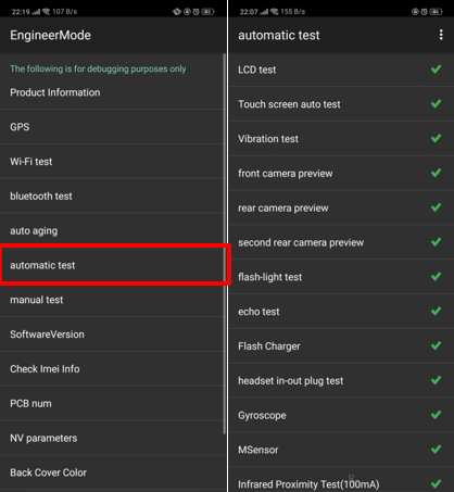 8.2.3 Automatically enter LCD,automatically enter the LCD test of the function test. Click on the screen to switch among red, green, blue, white, black, gray, gray scale, multicolor, and fruit colors, lines, highlights, black spots, etc. After the test is finished, the interface will automatically appear the “Confirm” dialogue box.
 8.2.4. Vibration Test
When the motor vibrates for 3 seconds, move the motor close to the ear. Test according to the above table. The “Confirm” dialog box will jump automatically after 3 seconds of the test. Select “PASS” if the test is passed. If there is noisy vibration, no vibration, or weak vibration, select "FAIL";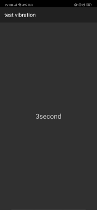 8.2.5. Touch Screen Automatic Test
The interface will jump to the touch screen automatic test after the last test was finished, and the mobile phone system will automatically test touch screen. After the test is passed, it will automatically jump to the next test item; if the test fails, the interface will not jump. Press the return key to enter “Confirm” Dialog box, and select "FAIL  8.2.6. Rear camera preview
After judging the result of the vibration, the preview interface automatically entered for 5 seconds. Test according to the above test requirements. Judge the test result when the machine enters automatically “Confirm” dialog box after 5 seconds. 8.2.7. Main rear camera
The preview interface of main rear camera will be automatically entered for 5 seconds after judging the front camera. Test according to the above test requirements. Judge the test result when the machine enters automatically “Confirm” dialog box after 5 seconds.  8.2.8. Sub rear camera
The preview interface of sub rear camera will be automatically entered for 5 seconds after judging the main rear camera. Test according to the above test requirements. Judge the test result when the machine enters automatically “Confirm” dialog box after 5 seconds.
8.2.9 .Echo test
In the echo test, if “Main MIC” is gray, the main MIC is being tested; Blow the air to the MIC hole on the bottom of the phone. If the receiver (earphone) sounds, the test is passed; Then click on the " sub MIC" to test the sub MIC and blow air to the sub MIC hole on the top of the phone. If the speaker sounds, the test is passed. Press the return key to enter the “Confirm” dialog box and judge the result.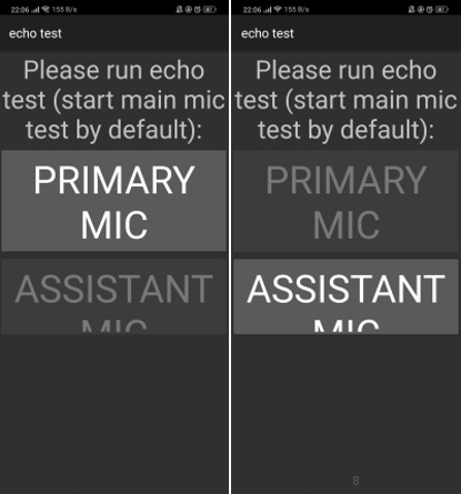 8.2.10. Flashlight test
The test interface of flashlight will be automatically entered for 5 seconds after judging the sub rear camera. Test according to the above test requirements. Judge the test result when the machine enters automatically “Confirm” dialog box after 5 seconds.
8.2.11. VOOC Test
Use the OPPO dedicated VOOC adapter and VOOC cable test. If the test is passed, it will automatically jump to the next test item. If the test fails, the interface will not jump. Press the return key to enter the “Confirm” dialog box and select "FAIL";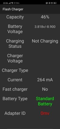 8.2.12. Earphone Plug Test
Enter the earphone plug-in test with the OPPO earphone and the interface will automatically jump to the next test item. If the test fails, the interface will not jump. Press the return key to enter the “Confirm” dialog box and select "FAIL"; 8.2.13 Sensor self-test and calibration
Enter the sensor self-test and calibration test ,the device will auto test after click the” operation not started”, if test OK , the interface will automatically jump to the next test item. If the test fails, the interface will not jump. Press the return key to enter the “Confirm” dialog box and select "FAIL"; 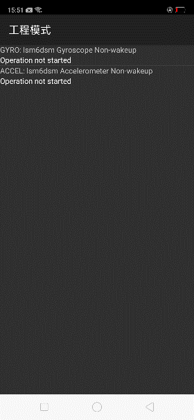 8.2.14 Gyro test
Hold the phone to draw a “8” shape in the gyro test interface. After the test is passed, it will automatically jump to the next test item; if the test fails, the interface will not jump. Press the return key to enter “Confirm” Dialog box, and select "FAIL 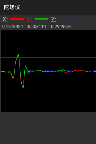 8.2.15 M Sensor
Shake the phone from the left to the right side in the M Sensor in the test interface. After the test passes, it will automatically jump to the next test item; if the test fails, the interface will not jump. Press the return key to enter “Confirm” Dialog box, and select "FAIL";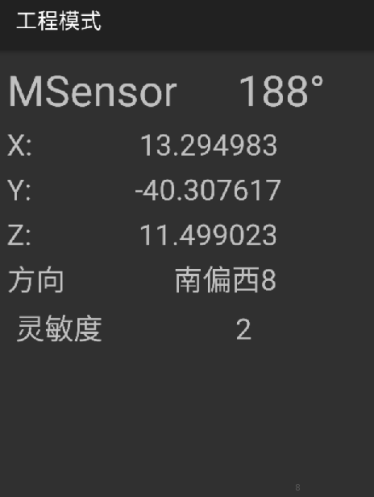 8.2.16 Infrared proximity test (100mA)
Put the phone on table, and use the hand cover the touch of top part, the screen change to green, After the test passes, it will automatically jump to the next test item; if the test fails, the interface will not jump. Press the return key to enter “Confirm” Dialog box, and select "FAIL";
8.2.17 Infrared proximity test (150mA)
Put the phone on table, and use the hand cover the touch of top part, the screen change to green , After the test passes, it will automatically jump to the next test item; if the test fails, the interface will not jump. Press the return key to enter “Confirm” Dialog box, and select "FAIL";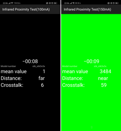 8.2.18 Button test
Several machines with visual buttons can only test 3 buttons: Power button, Volume Plus button and volume deduction button; Machines with physical buttons need to test 6 buttons to be tested which will be identified in the test. After the test passes, it will automatically jump to the next test item; if the test fails, the interface will not jump. Press the return key to enter “Confirm” Dialog box, and select "FAIL"; 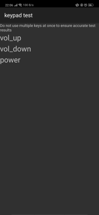 8.2.19 Fingerprint auto test
The interface will jump to the fingerprint automatic test, and the mobile phone system will automatically test fingerprint. After the test is passed, it will automatically jump to the next test item; if the test fails, the interface will not jump. Press the return key to enter “Confirm” Dialog box, and select "FAIL; 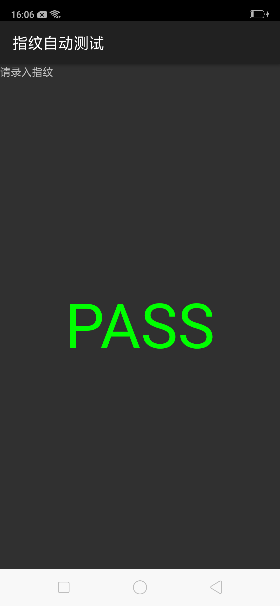 8.2.20 Audio& Video Test
Click the 20-4K(-3db)signal” to test the sound in the audio& video test interface. The interface will enter the “Confirm” dialogue box after tested for 5 seconds Then judge the test result;  8.2.21 Call Test
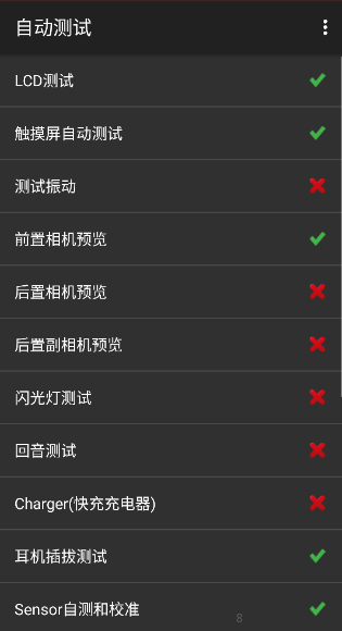
If the phone has been installed with the operator's SIM card, dial the corresponding operator's phone number. If no card is inserted, call the 112 test (It is recommended to install the sim card to call). Check according to requirements, press the return key to enter “Confirm” dialog box, and select the result of the judgment; 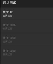 8.2.22 After the above 21 test items are tested, they will jump to the test result interface. If the test PASS project will show “√”, the test FAIL project will show “×”.
 Note: The aftersale devices calibration is needed when the motherboard /display screen assembly /touch film /fingerprint module is replaced;
Aftersale Devices Calibration:
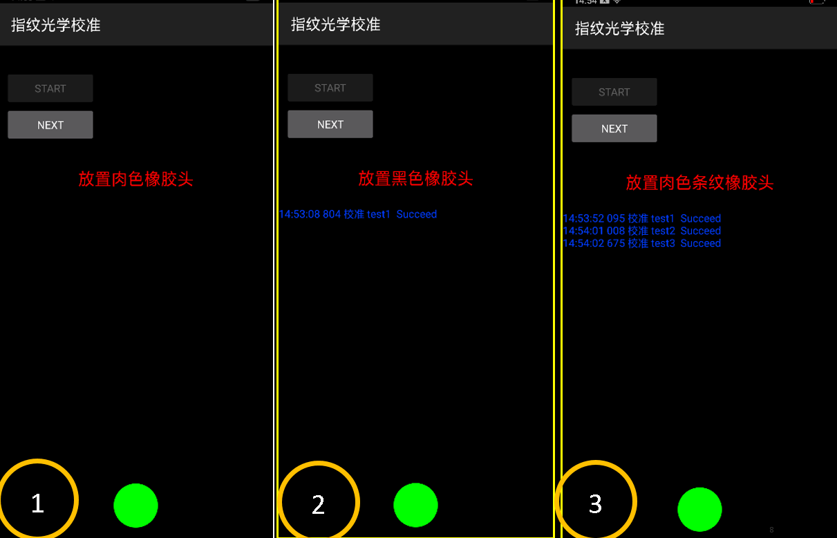
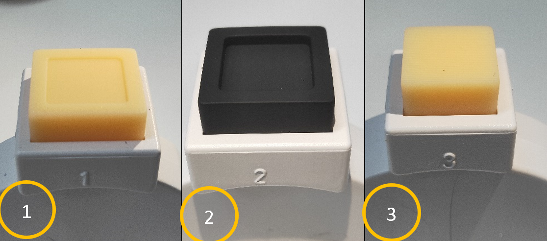
Click the aftersale device calibration, and enter “6776” when prompting” the module calibration need cali-devices, wrong calibration…”; and then tap “OK” to enter the interface “fingerprint light calibration “; Click the “start “ icon to start fingerprint light calibration;
Put the number 1 flesh colored rubber on touch Fingerprint spot when the device shows “put the flesh colored rubber”, and click the next ; If the test passes, put the number 2 black colored rubber on the touch Fingerprint spot when the device shows “put the black colored rubber”, click “next”;
If the test passes , put the number 3 flesh colored rubber button on the touch Fingerprint spot when the device shows “put the flesh colored rubber”, click “next”; If the test passes ,it will show “pass “and automatically return to fingerprint light calibration .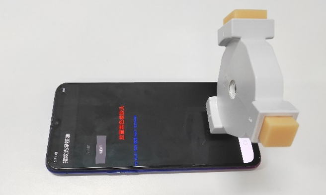
The purpose of this document is to help OPPO levels 1 and 2 maintenance technicians to carry out service to OPPO products. This Service Manual is to be used only by authorized OPPO maintenance service centers, and the content is confidential. Please note that OPPO provides also other guidance documents (e.g. Technical Service Bulletins) for maintenance service cooperative corporations, therefore, please follow the guidance regularly and comply with the given instructions. While every endeavor has been made to ensure the accuracy of this document, some errors may exist. Please keep in mind also that this documentation is continuously being updated and modified, please keep watching out for the newest version.
1.1 Warnings and Cautions
Please refer to the handset's user guide for instructions relating to operation, service and maintenance including important safety information. Note also the following:
Warnings:
1)Service centers may be required to install the handset's vehicle-mounted system in vehicles. Under certain fault conditions, the handset's RF signals may affect the operation of the vehicles' electric power management systems and anti–skid braking systems (ABSs). If necessary, consult the vehicle dealer/manufacturer to determine the immunity of vehicle electronic systems to RF energy.
2) The handset must not be operated in areas likely to contain potentially explosive atmospheres, such as petrol stations, gas stations and blasting areas.
3) Operation of any radio transmitting equipment, including handsets, may interfere with the functionality of the medical devices protected by industrial mechanisms. Consult the manufacturer of the medical device if necessary. Other electronic equipment may also be subject to interference.
1.2 Attention
1) Maintenance and calibration must be undertaken by qualified technicians only.
2) Ensure all work is carried out at an anti-static workstation and that an anti-static wrist strap is worn.
3) Use only approved materials as specified in the bill of materials (BOM) list.
4) Ensure all components, screws and insulators are correctly re-fitted after maintenance and calibration. Ensure all cables and wires are repositioned correctly.
Electrostatic discharge can easily damage the sensitive components of electronic products. Therefore, every service center has to take care of OPPO's ESD protection requirements. Also see ESD Protection Requirements in this Service Manual
2. General Repair Information
※In this section the technician will get some general hints to carry out repairs:
Customer service personnel can download and read product documentation on:Download and read the product guide or user manual.
Before starting the repair, you must enter the ESD Protected Area and connect your wristband. Use gloves to avoid corrosion and fingerprints. Protect windows and display screens with a film to avoid dust and scratches. When cleaning the metal pads, you have to use a soft cloth/ESD brush and isopropanol. It is not allowed to use an eraser because it scratches the surface and will lead later on to oxidation and corrosion. Mechanical parts (except shielding covers and bent parts), which cannot be repaired in the event of a failure, can only be replaced, if they are not soldered. After removing and maintaining the shielding covers, make sure to replace them with new ones. Otherwise, the high-frequency leakage can have an influence on the device. Always use original OPPO spare parts. Check the soldering joints of the parts, which are concerned regarding the indicated error (e.g. soldered connectors or switches) and re-solder them if necessary (only repair centers that can conduct lead-free soldering). Remove redundant soldering flux after soldering. Assemble the handset with the standard screw torque (see the Introduction of the Service Manual).
Always use your own equipment for testing where you are sure that it works. For complaints about charger function, please test the handset with your own charger to be sure if the handset or charger causes the malfunction. When doing the fault log entries, always note the fault code which caused the malfunction. The accuracy of this code will be a great help to quality improvement. (Please refer to the relevant files if necessary).
Many service documents are available on the FTP server: ftp://wxfuwu@172. 16. 103. 212:919.
3.Overview
3.1 Purpose
The manual mainly introduces the disassembly and assembly method of 18311 and derived models to guide aftersales to repair phones correctly and avoid unnecessary waste.
3.2 Overview Introduction to the Assembly
Schematic diagram of whole machine
3.3 Corresponding Relationship BOM
| SN | Material name | Specification model |
| 1 | OLED display | AMS641RW08-0 |
| 2 | Upper Motherboard cover | BD195 Black with padding |
| 3 | RF connecting cable | 50Ω 163mm FCCH100H1630A0 |
| 4 | Semi-finished FPC | PBD193-0-patch BD193 |
| 5 | Power key wiper PET sheet | BD195 single-sided adhesive |
| 6 | Semi-finished FPC | VBD193-0-patch BD193 |
| 7 | Volume key Anti-scratch PET sheet | BD195 single-sided adhesive |
| 8 | Motor silica sleeve | BD195 Black |
| 9 | Camera | Camera IMX398+GC2375H 16M+2M 19.21X11.00X5.90 6P+3P BTB OJS1266 |
| 10 | Semi-finished FPC | JBD167-0-patch BD167 |
| 11 | Vibration motor | 11.6×4×3.15 2.7V 30Ω Welded FPC |
| 12 | Motherboard pressing plate bracket | BD195 with insert |
| 13 | PCB semi-finished product | 2BD201-0 BD201 |
| 14 | Camera | IMX576 25.0M 7.82×7.70×4.92 5P BTB OOF1158 |
| 15 | Camera conductive fabric(front) | BD195 single-sided adhesive |
| 16 | Camera graphite sheet (front) | BD195 single-sided adhesive |
| 17 | Receiver grounding copper foil | BD195 single-sided adhesive |
| 18 | Camera conductive fabric(back) | BD195 single-sided adhesive |
| 19 | Receiver | 50mW 32Ω 10×8.5×2 plate spring A |
| 20 | SIM card holder | BD195 Red |
| 21 | Camera lens | BD195 Sapphire |
| 22 | Battery cover | BD195-TW Red black with padding |
| 23 | Lithium Battery | @ 3500mAh 3.85V 0.7C BLP689 416279 FA I724 |
| 24 | Bottom foam of battery bin | BD195 single-sided adhesive |
| 25 | USB all directional conductive foam cotton | BD195 single-sided adhesive |
| 26 | Semi-finished FPC | LBD193-0-patch BD193 |
| 27 | USB silicone case | BD195 Black |
| 28 | Semi-finished FPC | UBD201-0-patch BD201 |
| 29 | Semi-finished FPC | ABD201-0-patch BD201 |
| 30 | Machine tapping screw | CM 1.4×2.8 white nickel (head of diameter 2.5) locking3# |
| 31 | Semi-finished FPC | YBD193-0-patch BD193 |
| 32 | Antenna board pressing plate bracket | BD195 with molding |
| 33 | Speaker BOX | 1.5W 8Ω 28.35*25.1*3.639(2.979)mm |
| 34 | Fingerprint sensor module | GW9518 6.05×1.60×0.725 BTB 2# AD028 A102 UD |
| 35 | Display FPC silica sleeve | BD195 Black |
3.4 Material code and picture
| SN | Material Code | Material name | Material Picture |
|---|---|---|---|
| 1 | 4901926 | The upper cover component of motherboard | 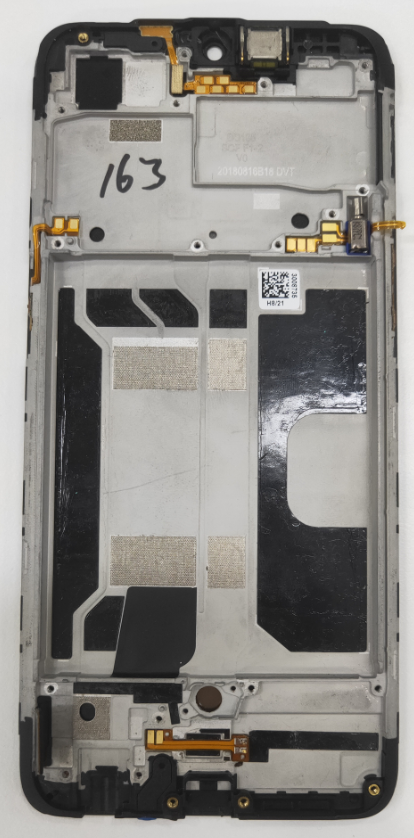 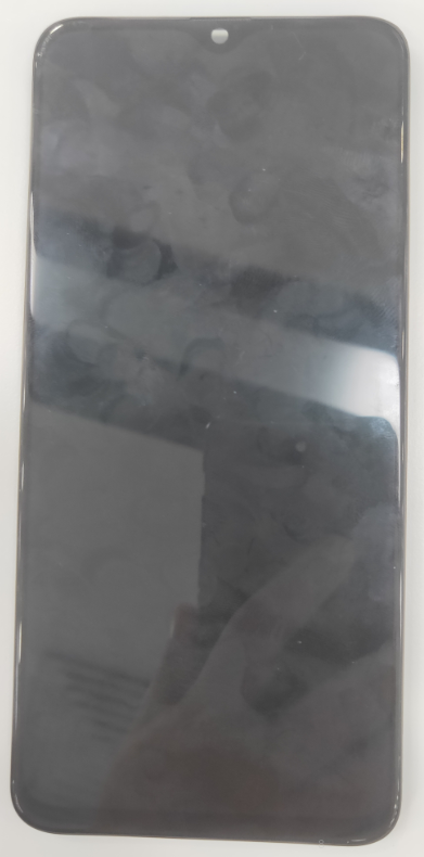 |
| 2 | 2180596 | RF connection cable | 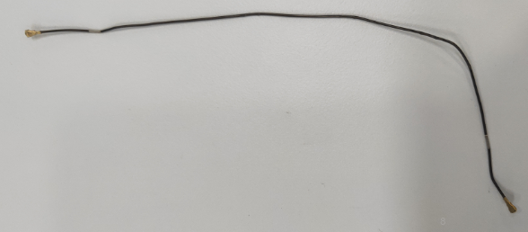 |
| 3 | 4902000 | USB Semi-finished FPC | 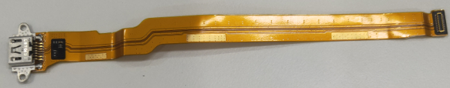 |
| 4 | 4962527 | Semi-finished FPC | 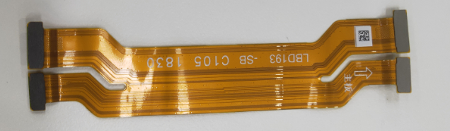 |
| 5 | 9490651 | Front Camera | 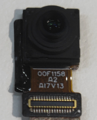 |
| 6 | 4962429 | Semi-finished FPCs | 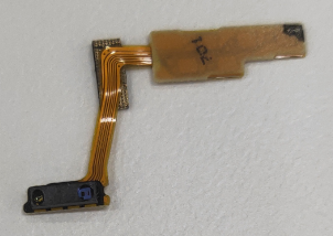 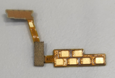 |
| 7 | 8710120 | Vibration motor | 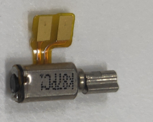 |
| 8 | 2929028 | Motherboard pressing plate bracket | 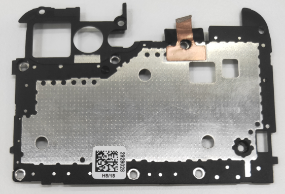 |
| 9 | 4901999 | PCB semi-finished components |
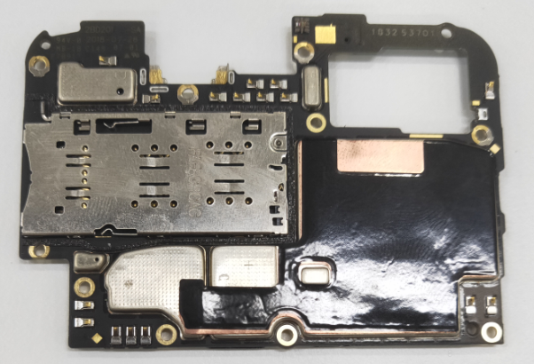  |
| 10 | 9490672 | Rear Camera | 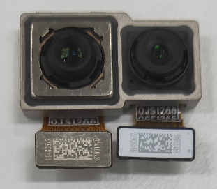 |
| 11 | 8520148 | Receiver | 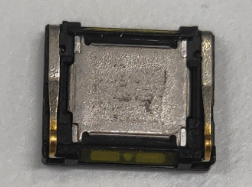 |
| 12 | Red :2929087 /blue : 2929022 /single SIM red: 2929197 /single SIM blue : 2929196 | SIM card holder | 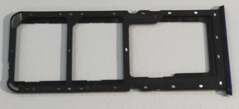 |
| 13 | 4901939 | Camera lens components | 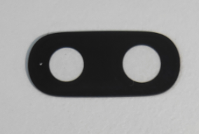 |
| 14 | 4901995/ 4901996/ 4901997/ 4901998/ | Battery cover components | 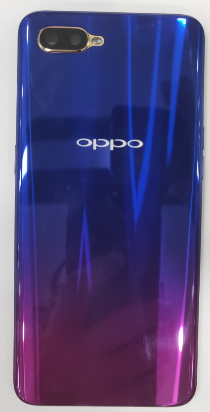 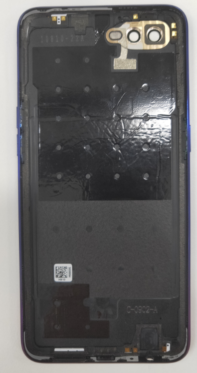 |
| 15 | 4901938 | Battery components | 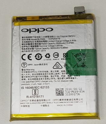 |
| 16 | 4962530 | Volume key Semi-finished FPC | 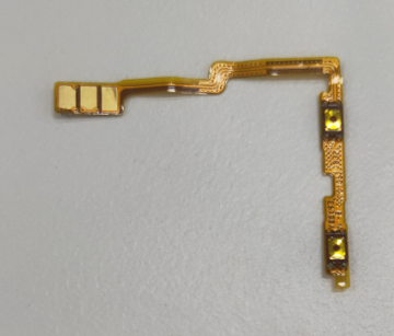 |
| 17 | 4874980 | USB silicon sleeve |  |
| 18 | 4962531 | Power key Semi-finished FPC | 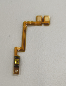 |
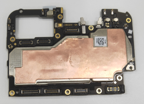
| 19 | 4962540 | PCB semi-finished product | 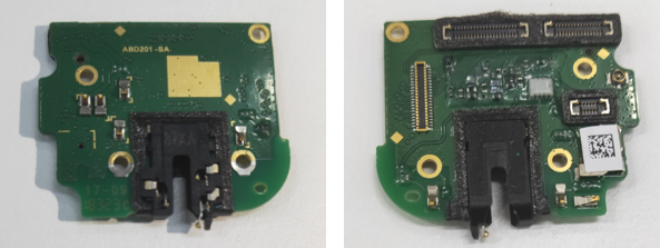 |
| 20 | 2929282 | Antenna board support (New | 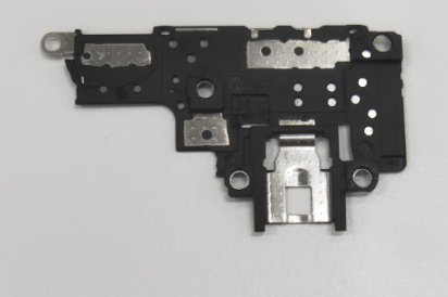 |
| 21 | 8511071 | Speaker BOX | 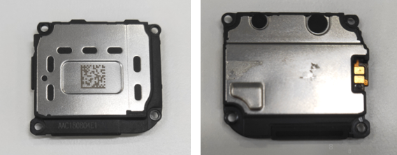 |
| 22 | 4902091 | Fingerprint sensor module | 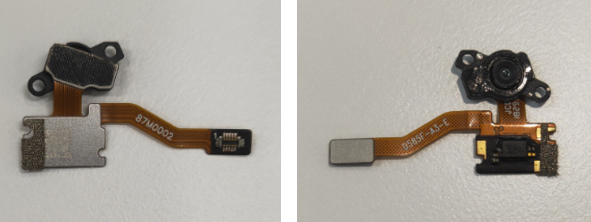 |
5. Disassembly procedure
| Procedure | sn | Picture | Operation Guidance |
|---|---|---|---|
| Preparation | 1 | 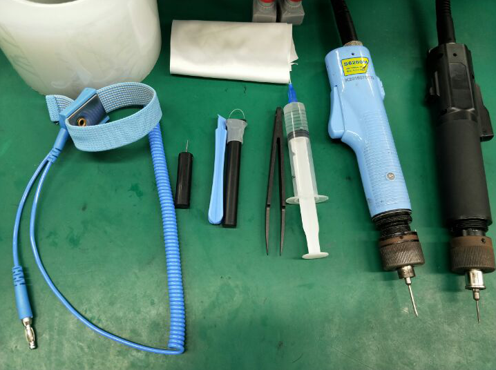 |
Disassembly tools required as shown below: ESD wristband (ESD Gloves), electricity screwdriver (cross behead), constant heating platform, 2.5 ml Alcohol syringe (blue plastic head), suction cup, flat plastic tweezers, card ejector pin, dust-free cloth, and disassembly rod (disassembling piece) etc. |
| 2 |
1.The phone must be shut down with the power option before disassembling.
2.Way to Shut Down: Press the power button then slide to power off.
|
||
| Remove battery cover | 3 | 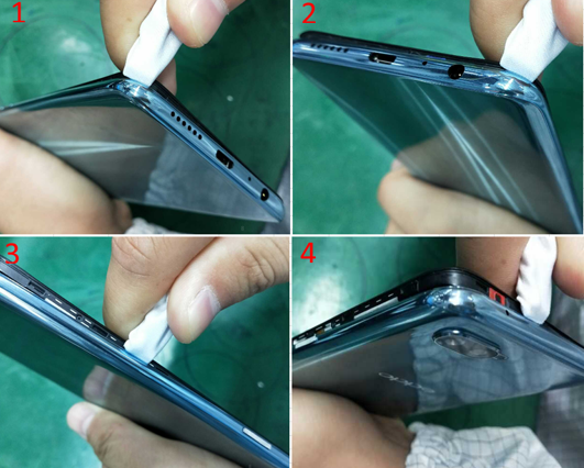 |
1. Use the ejector pin to remove the card holder; 2. Remove the battery cover : Wrap the head of the disassembler bar with a dust-free cloth and lift the back cover from the side corners of the rear cover as shown in the Figure, and slide the disassembly bar upwards along the long side of the cover to disassemble the back cover. Lift the lower cover from the corner of the upper side of the card holder with the disassembly bar, and slide the upper side to the straight side to disassemble the upper side buckle. Shake the back cover from side to side to remove the cover. 3. If the battery cover that has been disassembled cannot be attached in time, the double-sided tape of the battery cover needs to be covered with a low-viscosity protective film to avoid surface stickiness or foreign matter affecting the bonding performance of the battery cover; 4. Precautions for disassembling the back cover::It is necessary to check the appearance, especially paint-off or crack on the earphone jack; |
| Disassemble the motherboard bracket | 4 | 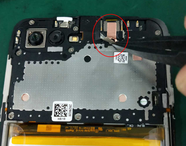 |
Tear off the receiver conductive Copper foil on the bracket; then use the electric screwdriver to remove the screws. Remove the Motherboard bracket;
|
| Disassemble battery | 5 | 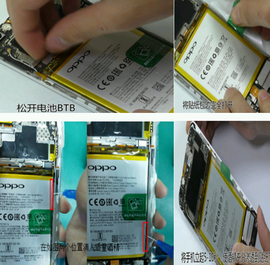 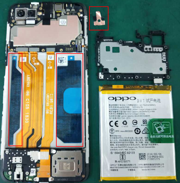 |
1. Open the battery BTB and pull out the easy-tore paper handle beside the battery. Inject a syringe of 0.2ml alcohol in the positions of red box. Stand the phone for 5-10S to let the alcohol penetrate under the sticker; 2. After standing, pull out the handle and pull the battery slowly, (Note: the battery should be pulled straight as far as possible and avoid pulling the battery vertically to cause the battery to deform). Remove the battery to the rear slowly (Pay attention to avoid the wrinkles of the battery wrapper); and then immediately paste the battery compartment with the double-sided adhesive release paper after the battery is removed and then tear off the bottom support cushion in the battery compartment. |
| Disassemble motherboard and camera | 6 | 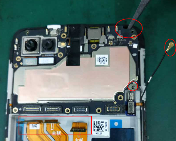 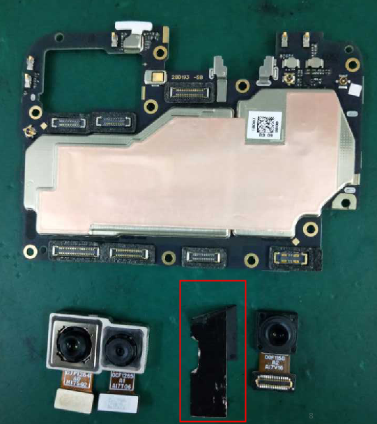 |
1. Use the electric batch to remove 1 pcs screw near the motor, remove the RF buckle on the motherboard , and use the plastic tweezers to remove the RF wire from the slot; The clamp on the motherboard needs pressing to gently pull the RF line out of the clamp; 2. Disassemble the 3pcs BTB buckle on the motherboard side of the USB board and the BTB buckle on the antenna board end; 3. Remove the motherboard by plastic tweezers from right side, and remove the front camera conductive sheet , then open the two rear camera BTB buckles from the long side of the BTB buckle and remove the rear camera from the motherboard; |
| Disassemble USB board and antenna board bracket & speaker BOX | 7 | 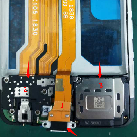 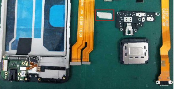 |
1. Use the electric batch to remove 9 pcs screws, then removed the USB FPC conductive sheet , 2. Remove the USB board FPC; 3. Remove the sound box bracket; 4. Disassemble the BTB buckle on the antenna board side of the main FPC, and remove the main FPC, and cover it with release paper; |
| Disassemble antenna board or fingerprint | 8 | 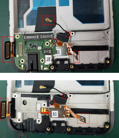 |
|
| Disassemble motor & key FPC and receiver | 9 | 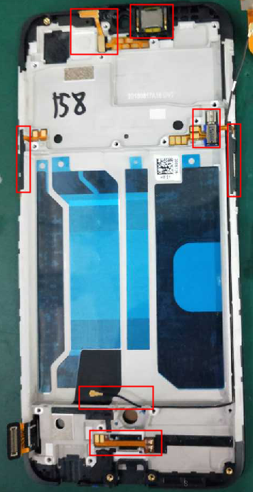 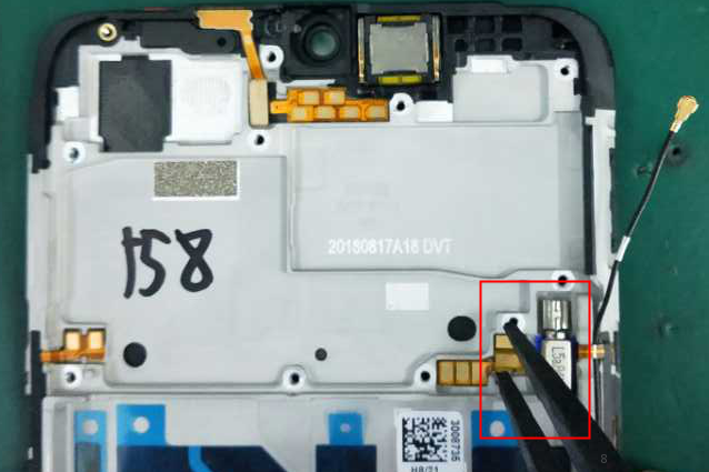 |
|
All parts of the machine as shown below:
6. General precautions
(1) All accessories, including double-sided adhesive, graphite sheet, copper foil, conductive cloth, foam, once disassembled, cannot be reused;
(2) All the appearance of pieces must be checked after removal;
(3) All electronic components must be tested after the functions are tested;
(4) Disassembling parts must be marked with the assembly mark according to the general specification: defective products make bad identification distinction, so as not to mix;
7. Assembly Procedure
7.1. Take the upper cover assembly and power key FPC, assemble the power key FPC to upper cover assembly, and assemble the volume key FPC(Pay attention not to paste the volume key on the upper side wall, and assemble it after the RF cable is installed.); Then assemble the light sensor and receiver (Pay attention to the direction of the receiver's shrapnel );assemble the motor Silicone Case to motor , and then assemble the motor to the upper cover assembly;
8 .Functional Test after maintenance
After maintenance, identify the faults described by the user and test other functions of the handset.
Return it to the user, only when the phone proves qualified after testing.
8.1 Appearance Inspection
Verify whether the handset display screen has abnormalities such as stains, wide gap, cracked shell, cracked key, scratch and whether the USB port falls off.
8.2 Function Inspection
8.2.1 Eject the SIM card tray with an eject pin and insert two SIM cards, and the handset will automatically reboot or you need to tap "Reboot".
8.2.2 The handset reboots and enters the idle screen.tap the dialing icon and enter *#807#, on the dial pad to enter the after-sale engineering mode ,it’s will auto-test ,if the phone with passcode , we tap dialing icon and enter *#899# on the dial pad to enter the after-sale engineering ,and choice the auto-test
When the motor vibrates for 3 seconds, move the motor close to the ear. Test according to the above table. The “Confirm” dialog box will jump automatically after 3 seconds of the test. Select “PASS” if the test is passed. If there is noisy vibration, no vibration, or weak vibration, select "FAIL";
The interface will jump to the touch screen automatic test after the last test was finished, and the mobile phone system will automatically test touch screen. After the test is passed, it will automatically jump to the next test item; if the test fails, the interface will not jump. Press the return key to enter “Confirm” Dialog box, and select "FAIL
After judging the result of the vibration, the preview interface automatically entered for 5 seconds. Test according to the above test requirements. Judge the test result when the machine enters automatically “Confirm” dialog box after 5 seconds.
The preview interface of main rear camera will be automatically entered for 5 seconds after judging the front camera. Test according to the above test requirements. Judge the test result when the machine enters automatically “Confirm” dialog box after 5 seconds.
The preview interface of sub rear camera will be automatically entered for 5 seconds after judging the main rear camera. Test according to the above test requirements. Judge the test result when the machine enters automatically “Confirm” dialog box after 5 seconds.
8.2.9 .Echo test
In the echo test, if “Main MIC” is gray, the main MIC is being tested; Blow the air to the MIC hole on the bottom of the phone. If the receiver (earphone) sounds, the test is passed; Then click on the " sub MIC" to test the sub MIC and blow air to the sub MIC hole on the top of the phone. If the speaker sounds, the test is passed. Press the return key to enter the “Confirm” dialog box and judge the result.
The test interface of flashlight will be automatically entered for 5 seconds after judging the sub rear camera. Test according to the above test requirements. Judge the test result when the machine enters automatically “Confirm” dialog box after 5 seconds.
8.2.11. VOOC Test
Use the OPPO dedicated VOOC adapter and VOOC cable test. If the test is passed, it will automatically jump to the next test item. If the test fails, the interface will not jump. Press the return key to enter the “Confirm” dialog box and select "FAIL";
Enter the earphone plug-in test with the OPPO earphone and the interface will automatically jump to the next test item. If the test fails, the interface will not jump. Press the return key to enter the “Confirm” dialog box and select "FAIL";
Enter the sensor self-test and calibration test ,the device will auto test after click the” operation not started”, if test OK , the interface will automatically jump to the next test item. If the test fails, the interface will not jump. Press the return key to enter the “Confirm” dialog box and select "FAIL";
Hold the phone to draw a “8” shape in the gyro test interface. After the test is passed, it will automatically jump to the next test item; if the test fails, the interface will not jump. Press the return key to enter “Confirm” Dialog box, and select "FAIL
Shake the phone from the left to the right side in the M Sensor in the test interface. After the test passes, it will automatically jump to the next test item; if the test fails, the interface will not jump. Press the return key to enter “Confirm” Dialog box, and select "FAIL";
Put the phone on table, and use the hand cover the touch of top part, the screen change to green, After the test passes, it will automatically jump to the next test item; if the test fails, the interface will not jump. Press the return key to enter “Confirm” Dialog box, and select "FAIL";
8.2.17 Infrared proximity test (150mA)
Put the phone on table, and use the hand cover the touch of top part, the screen change to green , After the test passes, it will automatically jump to the next test item; if the test fails, the interface will not jump. Press the return key to enter “Confirm” Dialog box, and select "FAIL";
Several machines with visual buttons can only test 3 buttons: Power button, Volume Plus button and volume deduction button; Machines with physical buttons need to test 6 buttons to be tested which will be identified in the test. After the test passes, it will automatically jump to the next test item; if the test fails, the interface will not jump. Press the return key to enter “Confirm” Dialog box, and select "FAIL";
The interface will jump to the fingerprint automatic test, and the mobile phone system will automatically test fingerprint. After the test is passed, it will automatically jump to the next test item; if the test fails, the interface will not jump. Press the return key to enter “Confirm” Dialog box, and select "FAIL;
Click the 20-4K(-3db)signal” to test the sound in the audio& video test interface. The interface will enter the “Confirm” dialogue box after tested for 5 seconds Then judge the test result;
If the phone has been installed with the operator's SIM card, dial the corresponding operator's phone number. If no card is inserted, call the 112 test (It is recommended to install the sim card to call). Check according to requirements, press the return key to enter “Confirm” dialog box, and select the result of the judgment;
Aftersale Devices Calibration:
Click the aftersale device calibration, and enter “6776” when prompting” the module calibration need cali-devices, wrong calibration…”; and then tap “OK” to enter the interface “fingerprint light calibration “; Click the “start “ icon to start fingerprint light calibration;
Put the number 1 flesh colored rubber on touch Fingerprint spot when the device shows “put the flesh colored rubber”, and click the next ; If the test passes, put the number 2 black colored rubber on the touch Fingerprint spot when the device shows “put the black colored rubber”, click “next”;
If the test passes , put the number 3 flesh colored rubber button on the touch Fingerprint spot when the device shows “put the flesh colored rubber”, click “next”; If the test passes ,it will show “pass “and automatically return to fingerprint light calibration .