ESD Equipment Installation Guidance on Service Centers
Note: This guide only applies to the installation of ESD protection equipment customized by OPPO Customer Service Centers.
Special Remarks: It is best to install a leakage-protection switch on the main line of this ESD device. The leakage-protection switch will check the current through the null and live wires at both ends. If the current passing is abnormal, indicating that there is leakage, the leakage protection switch will trip. This solution of disassembling the socket during installation involves safety issues. Therefore, after disconnecting the main switch, the electric pen must be used to test whether the port inside the socket is without current.
一、 ESD Equipment Overview
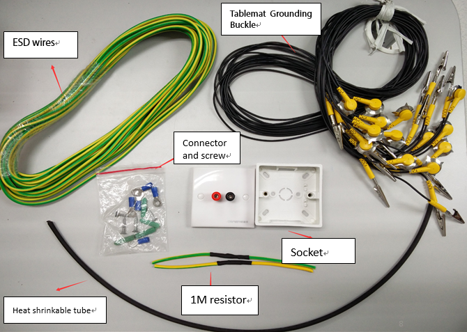
1. The ESD equipment customized by company contains the following 6 parts: ESD wires, grounding sockets (upper and lower parts), 1M Ω Resistor, Wire terminal and Screws, Tablemat Grounding Buckle, Heat Shrinkable Tube;
2. Special Remarks: Heat shrinkable tube has high temperature shrinkage, soft flame retardant, and resistance for heat and corrosion (Exposed wires can be wrapped by insulated tape (Price:0.4~0.5USD/volume) or heat shrinkable tube).
3. Usage Method for Heat-Shrinkable Tube: Wrap the wire with the heat-shrinkable tube from the place where the terminal is connected. The heat-shrinkable tube is set to a temperature of about 180 degrees to heat the heat-shrinkable tube. The length of the heat-shrinkable sleeve must be reserved for more than 1.5CM. The specific physical objects of the ESD installation accessories are shown in following picture:
二、Method for Testing the Current of Grounded GND (Easy) Danger! Electricity!
1. Way to judge the wire: Use a test pencil to test; if electric pen lights up when the power is on, the end lighting is the live wire.
Note: Generally, the triangular socket is connected with live wire, null wire and earth wire (as shown in Figure 2.1). Since the electricians may reverse the live wire and the null wire, please test with the test pen.
2. Measure whether the voltages of live and earth wire reach 200.( Based on local voltage)
The triangular socket pins connected with live wire, neutral wire and earth wire (as shown in Figure 2.1). Use the multi-meter AC voltage file to test the voltage of the live and earth wires. If the voltage is greater than 200 volts, the earth wire is well grounded to meet the installation standard of the electrostatic device. If the earth wire is not good enough, the installation of the static device is not satisfied. As shown in Figure 2.2 (the hot and ground lines should have a voltage of more than 200 volts)
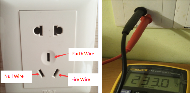
Figure 2.1 Figure 2.2
3. Theoretical voltage value reference:
Fire Wire - Null (x): x = 220v ± 20
Fire wire -Earth (y): y=220v±20
Null line - Earth line (z): 0.5v<z<5v
4. Special Case: If the voltage between live and null wire voltage itself does not reach 200V, the live and earth voltage value should refer to the voltage between the live-zero line. Example: Fire Wire - Earth (190V), the voltage of Fire - earth should not be lower than 180V.
This method is only applicable to the place where the earth wire exists; if there is no earth wire or the earth wire needs reinstalling, it needs to be installed and tested by professional electricians.
三、Connection Method for the Earth Wire on the Socket (Easy)
Note: The power supply must be cut off, and then use the electric pen to test whether the power has been completely cut off to avoid accidents.
After the test value has met the standard, you need to first lead the earth wire out. In order to ensure good contact of the earth wire, the earth wire should be led out from the wall socket.
1. Method:
1.1 Strip off the earth wire to get access to the earth wire;
1.2 After connected with the ESD wire, it needs to be tightly wrapped with insulating tape (The connection between wires must be wound for more than 4 circles, and the wrapped tape should wrap the bare earth wire to exceed 1.5CM)
As shown in Figure 3.1, 3.2, and 3.3, the wire T-shaped winding reference scheme is shown in Figure 3.4.
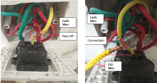
Figure 3.1 Figure 3.1
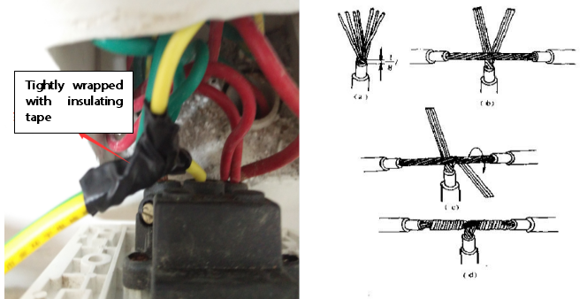
Figure 3.3 Figure 3.4
The earth wire to be connected needs to be connected to a 1MΩ resistor. The connection method of the resistor is described below.
四、Installation of 1MΩ Resistor
1. When connecting to a 1M Ω resistor, be careful not to bend the middle of the resistor to avoid breaking the resistor.
2. The connection of the resistor can be directly connected to the grounding socket cover (Figure 4.1).
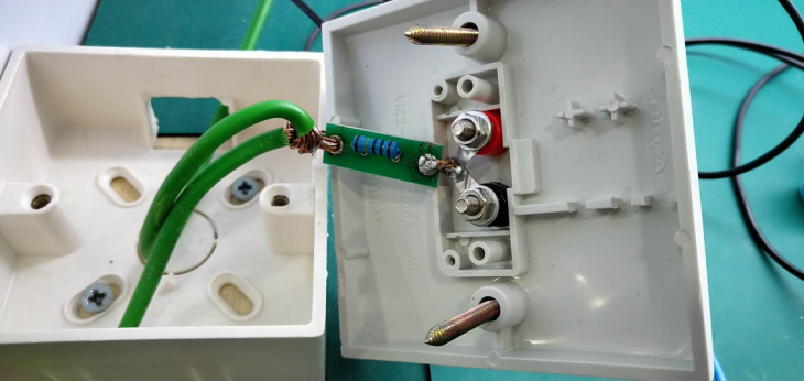
Figure 4.1
3. The wires on both sides of the resistor can be bent properly to make it easier to connect to the ESD wires during installation.
五、Installation of the Grounding Socket
1. When installing the grounding socket in the complete set of equipment, you need to find a good position. By observing the maintenance workbench, the position of the socket and the direction of the pre-judgment line, you can avoid unnecessary trouble during installation. The grounding socket consists of two upper and lower covers - as shown in Figure 5.1 and Figure 5.2.
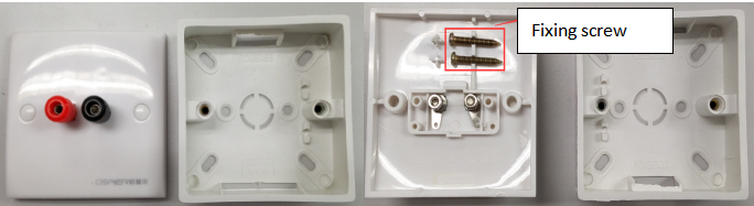
Figure 5.1 Figure 5.2
2. During installation, pre-select the position to fix the bottom cover of the grounding socket with screws (as shown in Figure 5.3), connect the top cover of the grounding socket to the 1MΩ resistor, and finally connect the top cover of the grounding socket to the lower cover with screws (as shown in Figure 5.3).
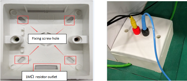
Figure5.3
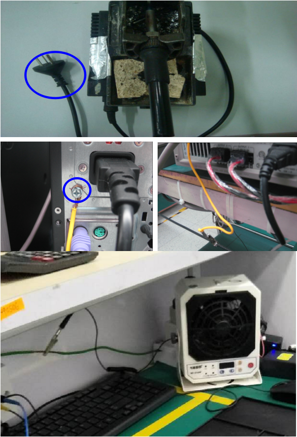
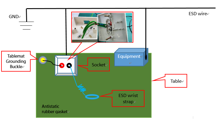
六、Installation Method for Equipment Grounding
1. Strip a small piece of insulation on the static wire to facilitate grounding of electrical equipment.
Warning:
In order to ensure that the equipment casing is not electrified, all electric tools and equipment must be connected with a power line with three cords; if it is not connected with such a power line, the casing must be grounded. The equipment grounding figure is as follows:
七、Installation of the Grounding Buckle of the Tablemat
The position of the pad grounding buckle installation does not need to be fixed in the same place. This guide is intended to make the installation easier and faster. When installing, first bend the grounding buckle, then puncture the pins into the table mat, and then use the pliers to press the grounding buckle (as shown in Figure 7.1).
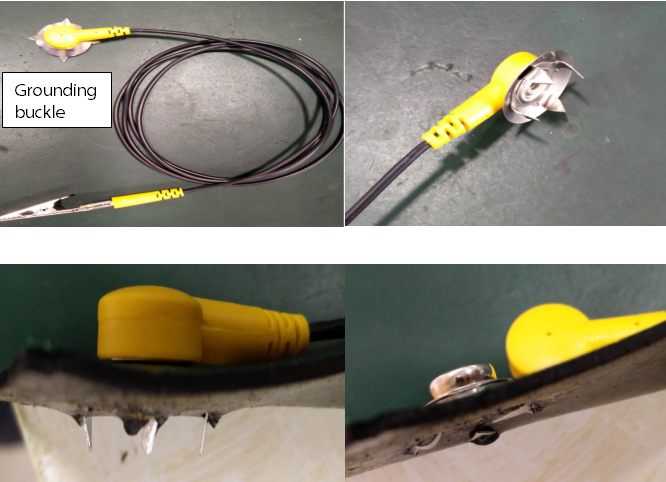
Figure 7.1
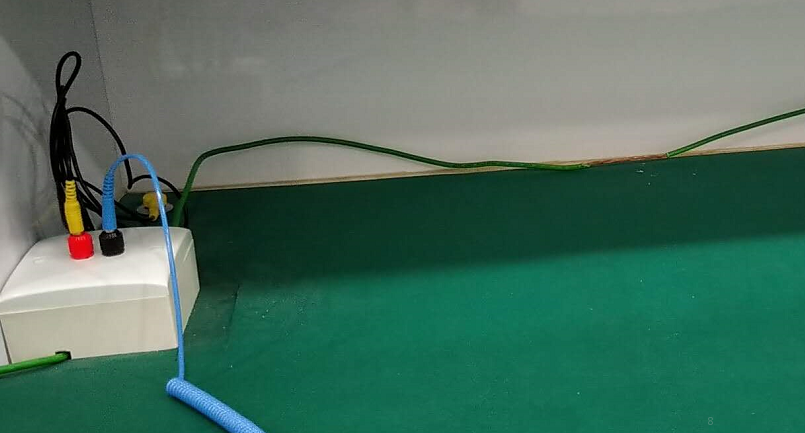
The overall effect after installation is shown in the figure below:
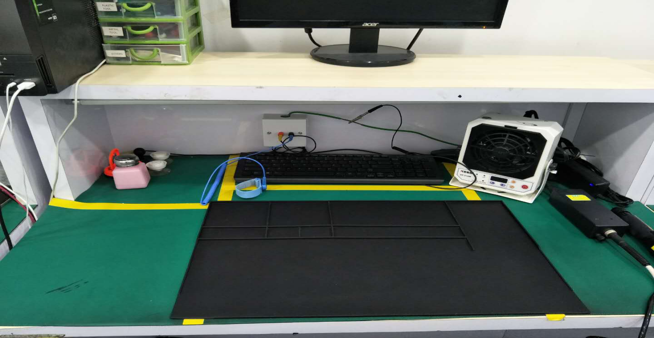
After installation, test the following numeric value.Please refer to the attachment for viewing.